POWER DISTRIBUTION
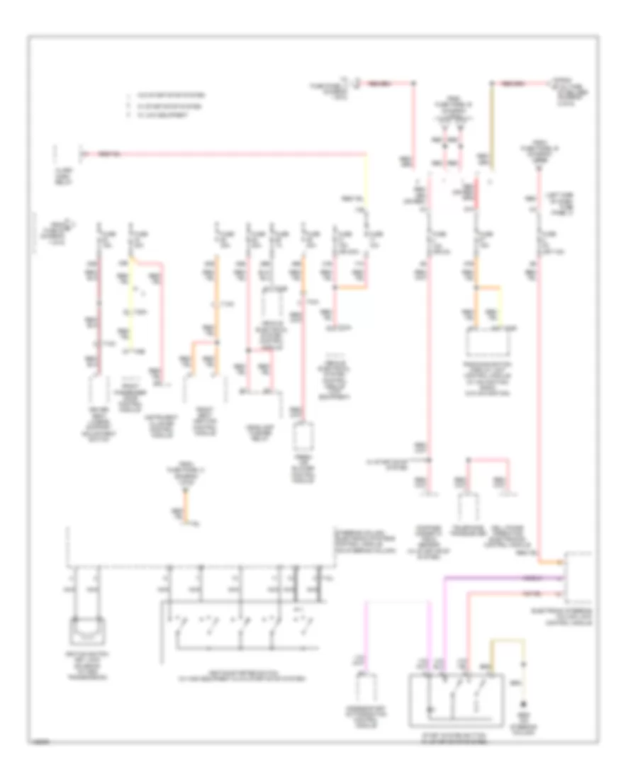
Power Distribution Wiring Diagram (1 of 6) for Volkswagen Jetta TDI Premium 2014

List of elements for Power Distribution Wiring Diagram (1 of 6) for Volkswagen Jetta TDI Premium 2014:
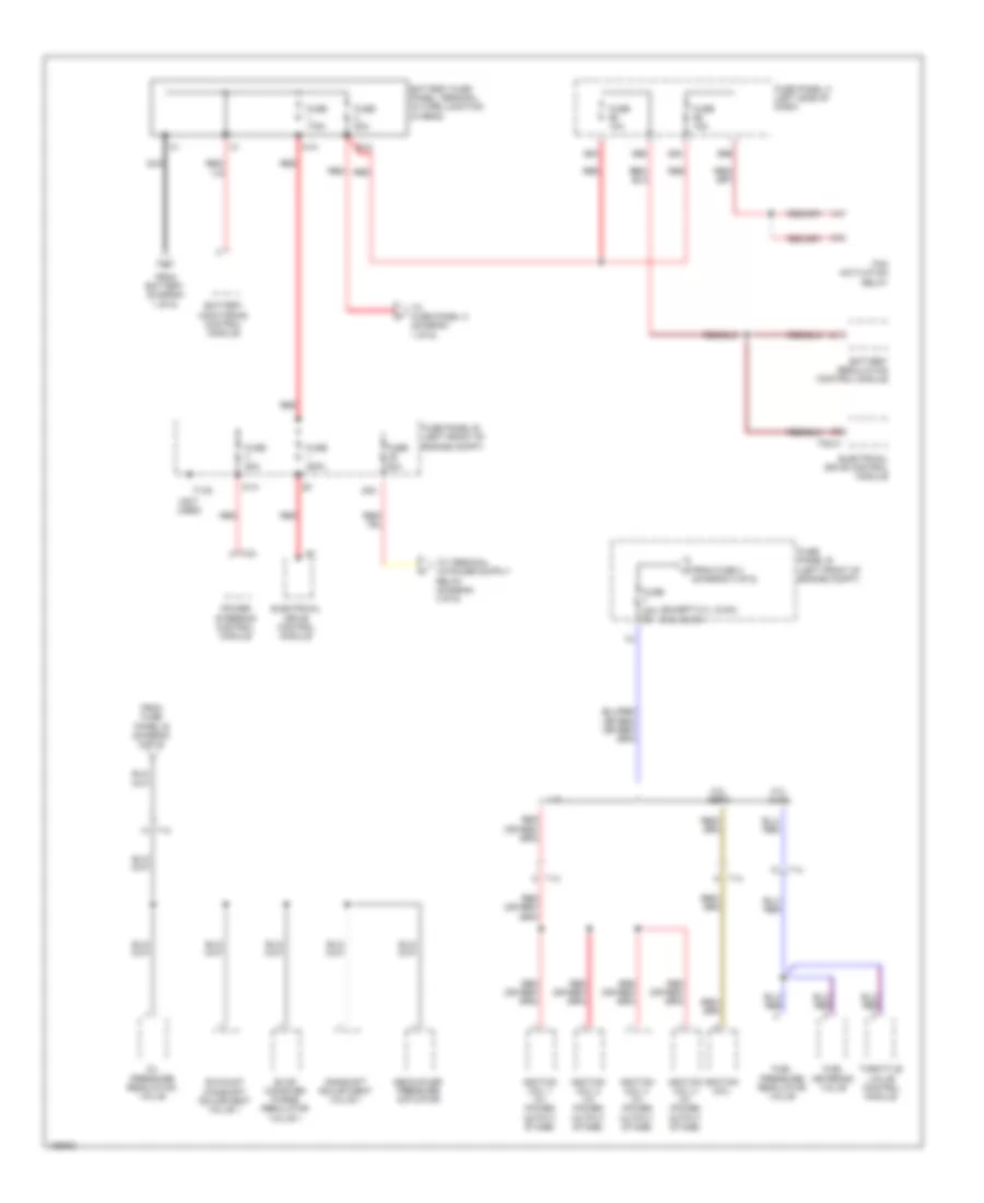
Power Distribution Wiring Diagram (2 of 6) for Volkswagen Jetta TDI Premium 2014
List of elements for Power Distribution Wiring Diagram (2 of 6) for Volkswagen Jetta TDI Premium 2014:
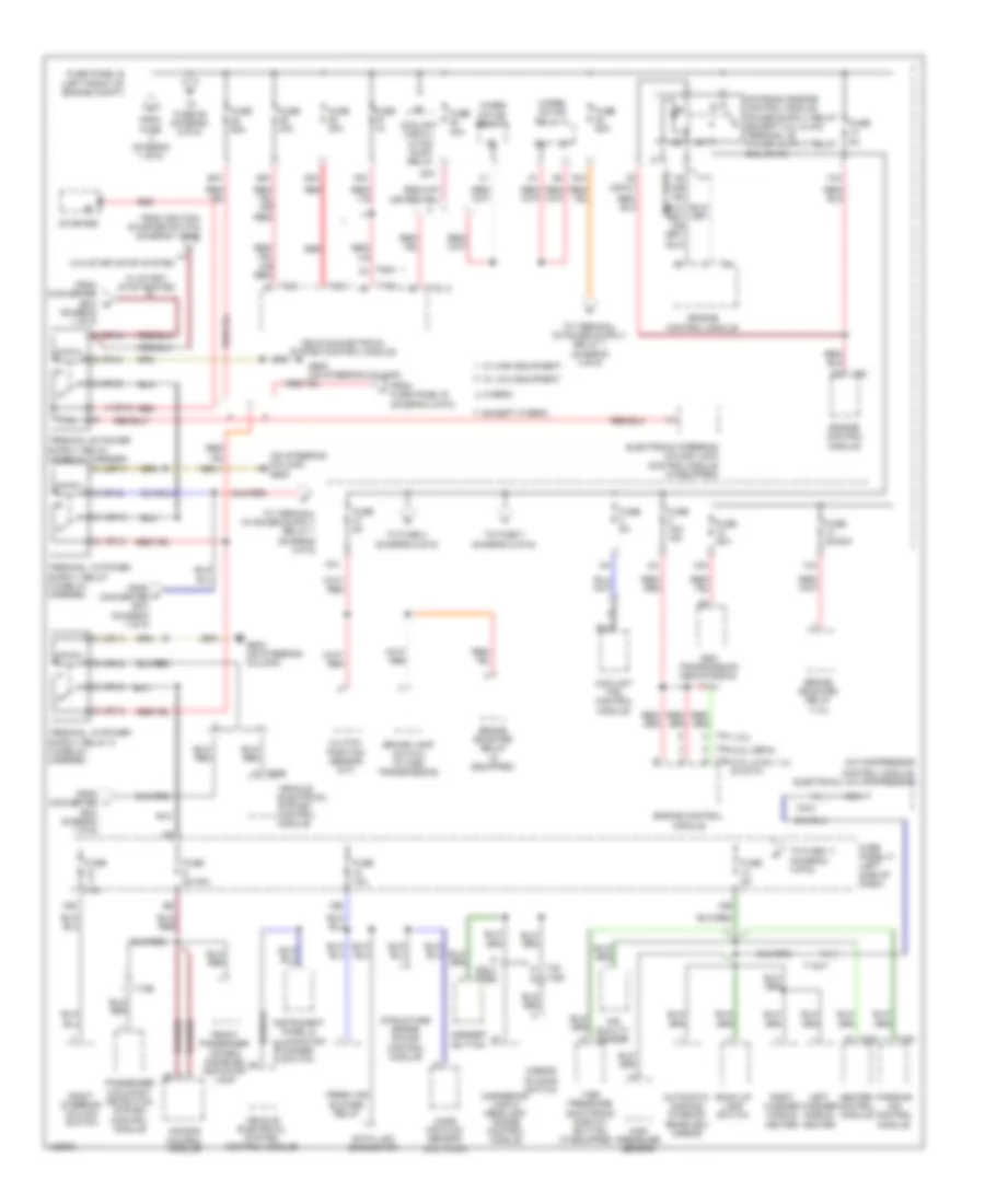
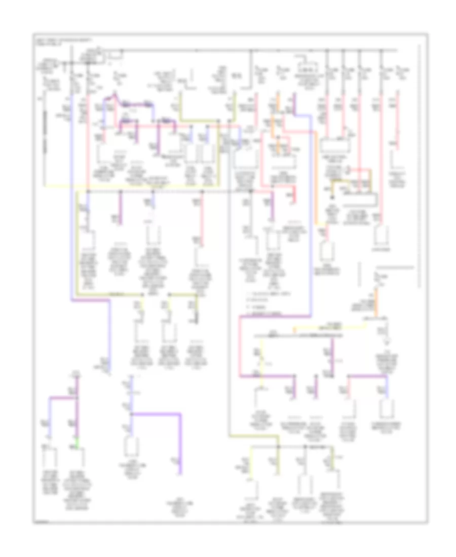
Power Distribution Wiring Diagram (3 of 6) for Volkswagen Jetta TDI Premium 2014
List of elements for Power Distribution Wiring Diagram (3 of 6) for Volkswagen Jetta TDI Premium 2014:
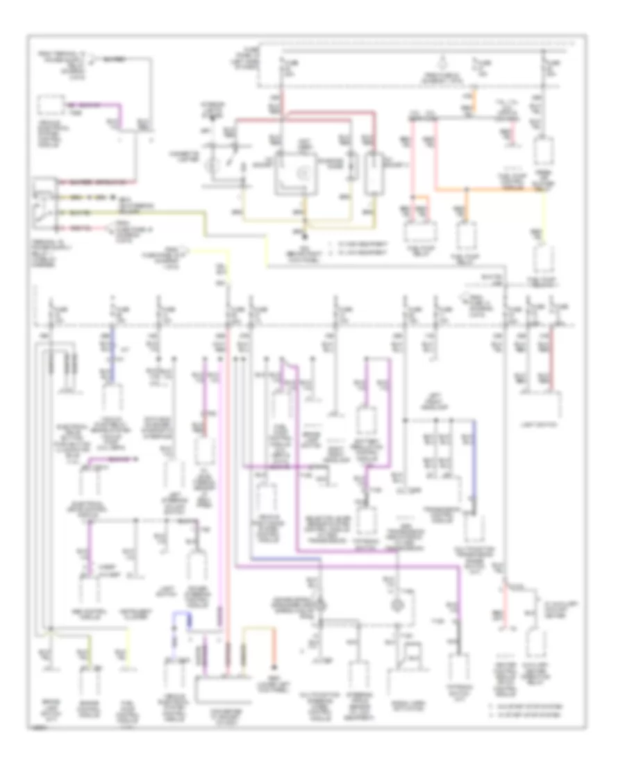
Power Distribution Wiring Diagram (4 of 6) for Volkswagen Jetta TDI Premium 2014
List of elements for Power Distribution Wiring Diagram (4 of 6) for Volkswagen Jetta TDI Premium 2014:
Power Distribution Wiring Diagram (5 of 6) for Volkswagen Jetta TDI Premium 2014
List of elements for Power Distribution Wiring Diagram (5 of 6) for Volkswagen Jetta TDI Premium 2014:
Power Distribution Wiring Diagram (6 of 6) for Volkswagen Jetta TDI Premium 2014
List of elements for Power Distribution Wiring Diagram (6 of 6) for Volkswagen Jetta TDI Premium 2014: