POWER DISTRIBUTION
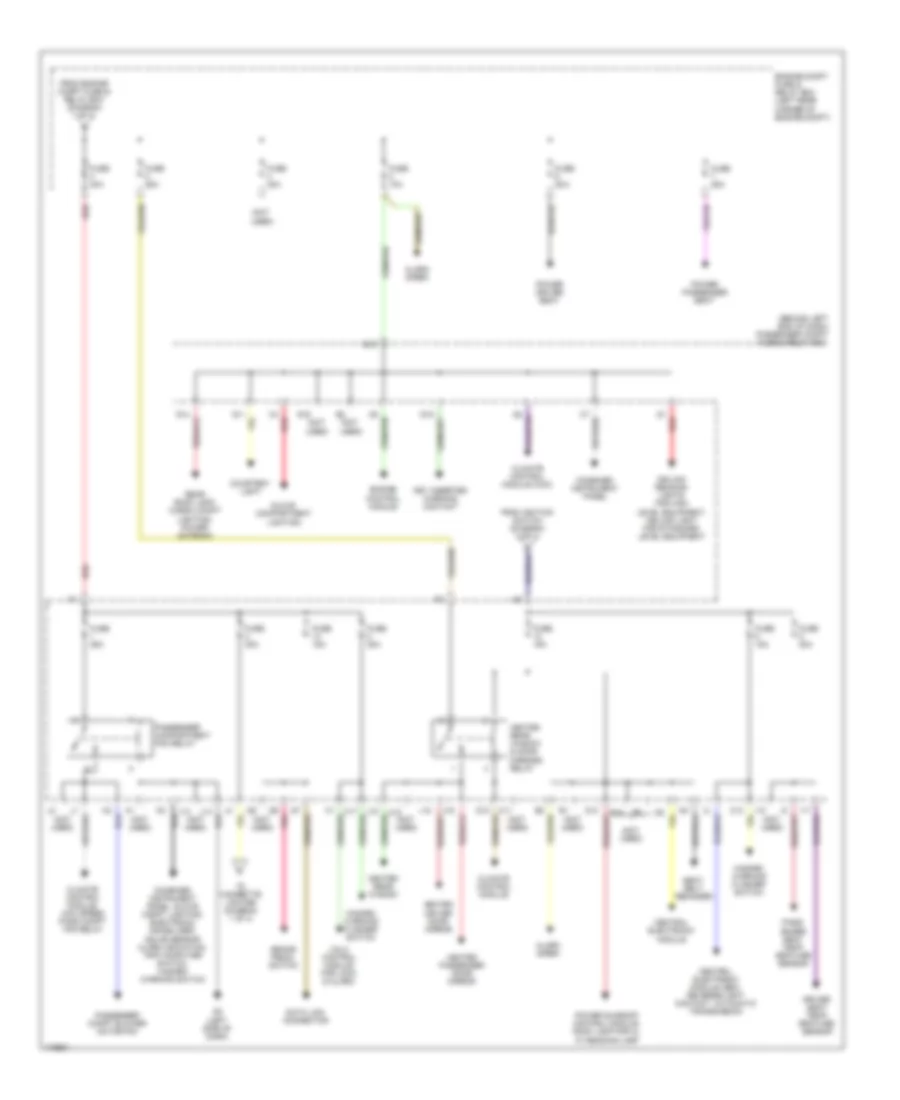
Power Distribution Wiring Diagram (1 of 3) for Volvo S40 2003

List of elements for Power Distribution Wiring Diagram (1 of 3) for Volvo S40 2003:
- (not used)
- Abs control module
- Ac compressor relay, ac condenser fan relay
- Audio amplifier
- Automatic transmission vacuum pump relay
- Battery
- Central electronic module (cem)
- Cigarette lighter
- Cigarette lighter relay (in passenger compartment fuse & relay box)
- Distribution rail
- Electric cooling fan speed 2 relay, electric cooling fan ac relay
- Electric cooling fan speed 1 relay,
- Engine compartment fuse & relay box (on left rear corner of engine compt)
- Engine control module
- Engine control module, automatic transmission vacuum pump
- Engine management system main relay (in engine compt fuse & relay box)
- Evap valve, heated oxygen sensors, idling valve
- From fuse 11 (diagram 3 of 3)
- From passenger compt fuse & relay box (diagram 2 of 3)
- From passenger compt fuse & relay box (diagram 3 of 3)
- Fuel pump
- Fuse
- Fuse 10a
- Fuse 120a
- Fuse 15a
- Fuse 20a
- Fuse 30a
- Fuse 40a
- Fuse 50a
- G1 (left side of dash)
- G15 (near battery)
- G5 (near battery)
- Generator
- Horn relay
- Immobilizer control module
- Power windows relay
- Radio
- Rear accessory outlet
- Red
- Starter
- Starter motor relay
- To engine compt fuse & relay box (diagram 2 of 3)
- To ignition switch (diagram 3 of 3)
- Transmission control module (tcm)
- Ultrasonic glass breakage sensor control module, vgla control module for locks & alarm, key inserted warning relay
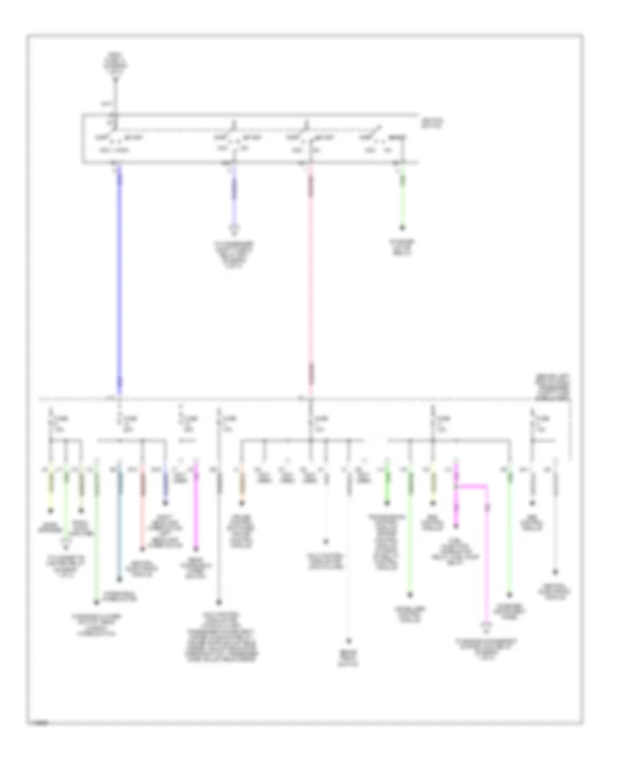
Power Distribution Wiring Diagram (2 of 3) for Volvo S40 2003
List of elements for Power Distribution Wiring Diagram (2 of 3) for Volvo S40 2003:
- (behind left end of dash) passenger compt fuse & relay box
- (not
- (not used)
- Alarm siren
- Brake pedal switch
- C11
- C12
- C17
- Ceiling reading lights for high level equipment, ceiling light for standard level equipment
- Central electronic module
- Central electronic module (cem), reverse light contact, automatic transmission
- Climate control module
- Climate control module (ccm)
- Climate control module, max speed pass compt fan relay
- Combined instrument panel
- Combined instrument panel, glove compt lighting, electronic immobilizer/ solar sensor alarm indication, trip computer switch, hazard warning switch
- Courtesy light
- Data link connector
- Driver seat temp- erature sensor
- E10
- E14
- Engine compt fuse & relay box (left rear corner of engine compt)
- Engine control module
- From engine compt fuse & relay box (diagram 1 of 3)
- From ignition switch (diagram 3 of 3)
- Fuse 10a
- Fuse 15a
- Fuse 20a
- Fuse 25a
- Fuse 30a
- Fuse 40a
- G11
- G12
- G13
- G14
- G15
- G16
- G2 (left side of dash)
- Glove compartment lighting
- Hazard warning flasher switch
- Heated driver door mirror
- Heated passenger door mirror
- Heated rear window
- Heated rear window & door mirrors relay
- I17
- I18
- J13
- J14
- J15
- J18
- Key inserted warning contact
- Pass- enger seat temp- erature sensor
- Passenger compartment fan relay
- Passenger compt blower motor fan
- Pnk
- Power driver seat
- Power passenger seat
- Power sunroof control module, roof lamp for hl w/ reading lamp
- Rear roof lamp, cargo compt lighting, power antenna
- Red
- Seat belt reminder
- To cigarette lighter (diagram 1 of 3)
- Used)
- Vgla control module for lock & alarm
Power Distribution Wiring Diagram (3 of 3) for Volvo S40 2003
List of elements for Power Distribution Wiring Diagram (3 of 3) for Volvo S40 2003:
- (behind left end of dash) passenger compt fuse & relay box
- (not used)
- 15/1
- 15/2
- Abs control module
- Acc
- Bass speaker
- Brake pedal switch
- Central electronic module
- Combined instrument panel
- Cruise control switches, cruise control module
- E11
- E13
- E15
- From fuse 14 (diagram 1 of 3)
- Fuel injection/ combustion relay, fuel pump relay
- Fuse 10a
- Fuse 15a
- Fuse 20a
- I12
- I13
- I14
- I15
- I16
- I22
- Ignition switch
- Immobilizer control module
- J10
- J11
- J12
- Off
- Radio, audio amplifier
- Rear windshield wiper switch
- Right headlamp wiper motor, left headlamp wiper motor
- Srs control module
- Start
- Starter motor (relay)
- To cigarette lighter relay (diagram 1 of 3)
- To engine management system main relay (diagram 1 of 3)
- To passenger compt fuse & relay box (diagram 2 of 3)
- Transmission control module, engine control module, dynamic stability control module
- Vgla control module for lock & alarm
- Vgla control module for locks & alarm, passenger power seat, power windows relay, driver door adjustable mirror, adjustable door mirror switch, passenger door adjustable mirror
- Windshield wiper motor
- Windshield wiper switch, rear window wiper switch