POWER DISTRIBUTION
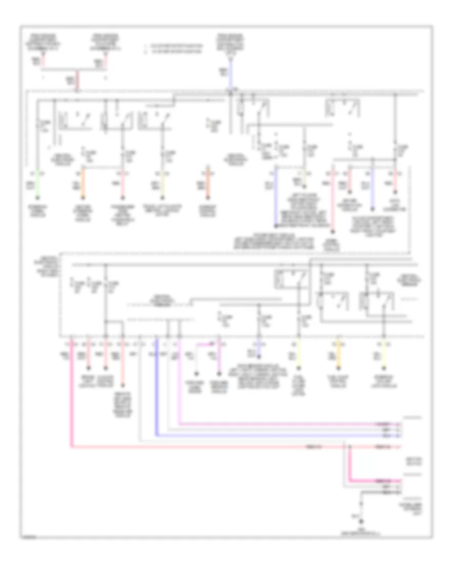
Power Distribution Wiring Diagram (1 of 4) for Volvo S60 T6 R-Design 2014

List of elements for Power Distribution Wiring Diagram (1 of 4) for Volvo S60 T6 R-Design 2014:
- Accelerator pedal sensor
- Alternator control module & starter motor
- Auto dimming rearview mirror
- Auxiliary lights relay
- Battery
- Battery fuses
- Battery monitoring sensor (bms)
- Brake control module
- Central electronic module
- Central electronic module (right end of dash)
- Climate control system relay
- Cold zone (diagram 4 of 4)
- Cooling fan control module
- Electrical power steering module
- Electrical power steering module (eps)
- Engine compartment distribution box (left side of engine compt)
- Engine control module
- Engine management system main relay
- Fan control module & passenger compartment fan motor
- Feed relay
- Forward aimed radar
- Forward sensing module & closing velocity module
- From a fuse a7 (diagram 1 of 4)
- From engine compartment cold zone (diagram 4 of 4)
- Fuse a1 50a
- Fuse a2 50a
- Fuse a3 60a
- Fuse a4 60a
- Fuse a43 80a
- Fuse a44 100a
- Fuse a5 60a
- Fuse a6 (not used)
- Fuse a7 100a
- Fuse b11 40a
- Fuse b12 40a
- Fuse b13 40a
- Fuse b14 20a
- Fuse b16 10a
- Fuse b17 20a
- Fuse b18 5a
- Fuse b19 5a
- Fuse b20 10a
- Fuse b21 10a
- Fuse b23 5a
- Fuse b27 5a
- Fuse b28 20a
- Fuse b29 15a
- Fuse b30 10a
- Fuse b31 15a
- Fuse b32 15a
- Fuse b34 30a
- Fuse b8 40a
- Fuse b9 30a
- Fuse f18 10a
- Fuse f19 5a
- Fuse f20 7.5a
- Fuse pf1 150a
- Fuse pf2 150a
- Headlight washer motor relay
- Headlight washer motor relay & driver side heated windscreen relay
- Heated windshield washer nozzle
- Horn relay
- Left front lamp housing
- Light switch module
- Nca
- Occupant weight sensor
- Passenger side heated windscreen relay
- Ptc element
- Ptc element & heated rear seat switch
- Red
- Right front lamp housing
- Speed dependent power steering control module
- Starter motor relay (w/o start/ stop function)
- To cargo compartment distribution box (diagram 4 of 4)
- To central electronic module (diagram 2 of 4)
- To engine compartment m
- To fuse a43 (diagram 1 of 4)
- To passenger compartment distribution box (diagram 3 of 4)
- Transmission control module
- W/ start/ stop function
- W/ start/stop function
- W/o start/stop function
- Wiper motor module
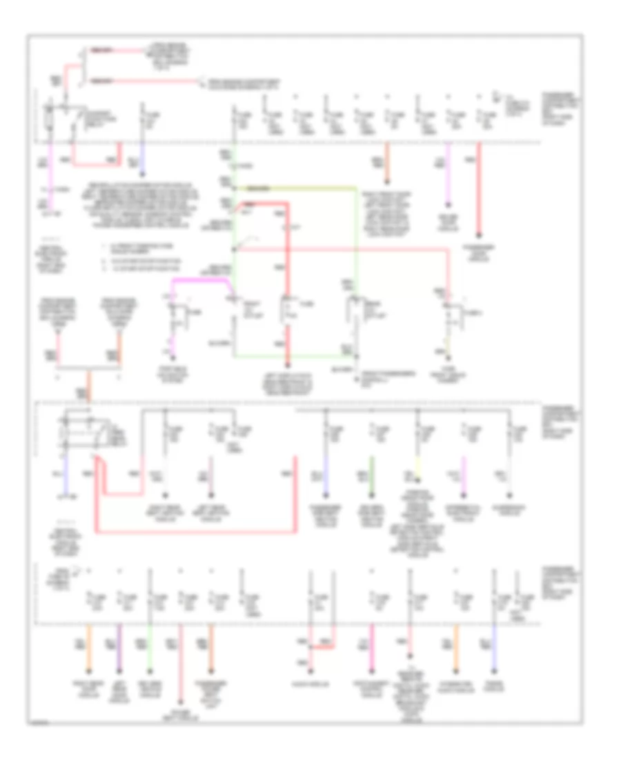
Power Distribution Wiring Diagram (2 of 4) for Volvo S60 T6 R-Design 2014
List of elements for Power Distribution Wiring Diagram (2 of 4) for Volvo S60 T6 R-Design 2014:
- Brake light contact
- Central electronic module
- Central electronic module (right end of dash)
- Climate control module
- Data link connector
- Driver information module
- Forward aimed radar
- Forward sensing module
- From engine compartment cold zone (diagram 4 of 4)
- From engine compartment distribution box (diagram 1 of 4)
- Fuel filler cover lock motor
- Fuel pump control module
- Fuse f1 (not used)
- Fuse f10 15a
- Fuse f11 10a
- Fuse f12 10a
- Fuse f13 20a
- Fuse f14 5a
- Fuse f15 15a
- Fuse f16 5a
- Fuse f22 5a
- Fuse f23 20a
- Fuse f24 5a
- Fuse f3 7.5a
- Fuse f4 5a
- Fuse f5 10a
- Fuse f6 7.5a
- Fuse f7 7.5a
- Fuse f8 10a
- Fuse f9 15a
- G83 (driver's door sill)
- Glove compartment lighting, left front courtesy lighting & right front courtesy lighting
- Heated steering wheel module
- Ignition switch
- Immobilizer antenna unit
- Left folding head restraint motor, right folding head restraint motor, left rear head restraint solenoid & right rear head restraint solenoid
- Passenger side heated windshield relay
- Power seat module, left side cargo compartment lighting power passenger seat switch unit & driver's door power window switches
- Rain sensor module, left vanity mirror lighting, right vanity mirror lighting, rear reading light, ceiling light & dome lighting switch unit
- Red
- Remote keyless entry & remote receiver module
- Siren control module
- Steering column lock module
- Steering wheel module
- Sunroof control module
- Trunk lid/tailgate central locking motor
- W/ start/stop function
- W/o start/stop function
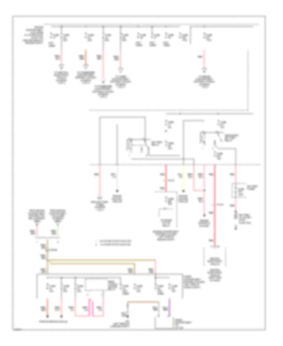
Power Distribution Wiring Diagram (3 of 4) for Volvo S60 T6 R-Design 2014
List of elements for Power Distribution Wiring Diagram (3 of 4) for Volvo S60 T6 R-Design 2014:
- (front passenger's door sill) g15
- (not used)
- 74/504
- 74/530
- 74/7
- 9x/1
- Audio module
- Central electronic module (right end of dash)
- Comfort functions relay
- Differential electronic module
- Driver door module
- Driver's side seat heating module
- Feed rear relay
- From engine compartment cold zone (diagram 4 of 4)
- From engine compartment distribution box (diagram 1 of 4)
- From g fuse c9 (diagram 3 of 4)
- Front 12v outlet
- Fuse
- Fuse 2
- Fuse c1 40a
- Fuse c10 20a
- Fuse c11 20a
- Fuse c12 7.5a
- Fuse c13 20a
- Fuse c14 20a
- Fuse c15 (not used)
- Fuse c16 5a
- Fuse c17 10a
- Fuse c18 15a
- Fuse c19 5a
- Fuse c2 (not used)
- Fuse c20 15a
- Fuse c21 5a
- Fuse c22 15a
- Fuse c23 15a
- Fuse c24 15a
- Fuse c25
- Fuse c26 15a
- Fuse c27 15a
- Fuse c28 5a
- Fuse c29 15a
- Fuse c3 (not used)
- Fuse c30 10a
- Fuse c4 (not used)
- Fuse c5 (not used)
- Fuse c6 5a
- Fuse c7 (not used)
- Fuse c8 20a
- Fuse c9 20a
- Infotainment control module
- Integrated audio module
- Keyless vehicle module
- Left display/dvd head restraint & right display/dvd head restraint
- Left rear door module
- Left rear seat heating module
- Parking assistance module, parking assistance camera, left side obstacle detection control module & right side obstacle detection control module
- Passenger compartment distribution box (right side of dash)
- Passenger door module
- Passenger power seat switch unit
- Passenger side seat heating module
- Phone module
- Portable navigation system
- Power seat module
- Rear 12v outlet
- Recirculation damper motor module, left temperature damper motor module, right temperature damper motor module, defroster damper motor module, floor/ventilation damper motor module, air quality sensor, sunroof control module, clean light & mobile phone handsfree control module
- Red
- Right front door lock contact, left front door lock contact, left rear door lock contact & right rear door lock contact
- Right rear door module
- Right rear seat heating module
- Suspension module
- To fuse c10 (diagram 3 of 4)
- Tv receiver, remote digital audio receiver, digital audio broadcast module & audio module
- W/ front parking wide angle camera
- W/ start/stop function
- W/o start/stop function
- Wide front angle camera
Power Distribution Wiring Diagram (4 of 4) for Volvo S60 T6 R-Design 2014
List of elements for Power Distribution Wiring Diagram (4 of 4) for Volvo S60 T6 R-Design 2014:
- (not used)
- 74/316
- 74/504b
- Battery (w/ start/ stop function)
- Battery fuses
- Battery relay
- Cargo compartment 12v outlet
- Cargo compartment distribution box (left side of cargo compt)
- Central electronic module
- Central electronic module (right end of dash)
- Engine compartment cold zone (w/ start/stop function) (center rear of engine compt)
- Engine compartment distribution box (left side of engine compt)
- Engine control module
- Engine controls system
- From battery fuses (diagram 1 of 4)
- From engine compartment cold zone (diagram 4 of 4)
- From engine compartment distribution box (diagram 1 of 4)
- Fuse a1
- Fuse a1 30a
- Fuse a11 40a
- Fuse a2 30a
- Fuse a2 50a
- Fuse a3 30a
- Fuse a3 60a
- Fuse a4 (not used)
- Fuse a4 60a
- Fuse a5 (not used)
- Fuse a5 60a
- Fuse a6
- Fuse a6 15a
- Fuse a7
- Fuse a8
- Fuse a9 30a
- Fuse b12 15a
- Fuse b34 30a
- Fuse m11 70a
- Fuse mf1 175a
- Fuse mf2 175a
- Fuse n/a
- Fuse pf4 150a
- G47 (left rear of luggage compt)
- Parking brake module
- Rear window heated relay
- Red
- Secondary battery relay
- Starter motor relay
- To cargo compartment distribution box (diagram 4 of 4)
- To central electronic module (diagram 2 of 4)
- To engine compartment distribution box (diagram 1 of 4)
- To passenger compartment distribution box (diagram 3 of 4)
- W/ start/stop function
- W/o start/stop function