POWER DOOR LOCKS
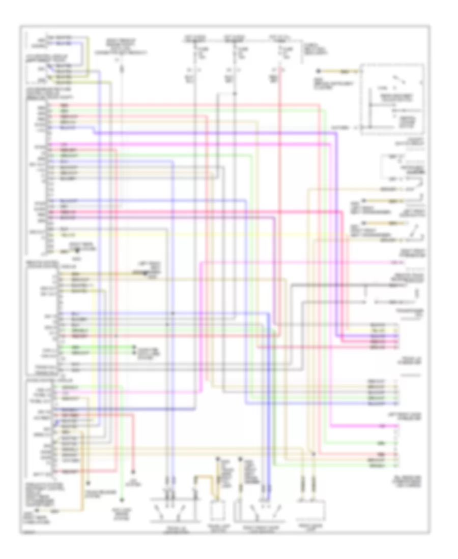
Power Door Lock Wiring Diagram for Mercedes-Benz C280 1997
List of elements for Power Door Lock Wiring Diagram for Mercedes-Benz C280 1997:
- (left front seat crossmember)
- (right rear of engine compt) data link connector (dtc readout)
- (right rear wheelhouse)
- +12v
- +5 v
- A/c rest
- A/c system
- Anti-lock brake system
- Arm
- Ata control module (left side of trunk)
- Batt (30)
- Can (h)+
- Can (l)-
- Central locking switch
- Cockpit switch group
- Computer data lines system
- Convenience feature control module (front of trunk compt)
- Diagn
- Disarm
- Dome
- Door
- Front dome lamp
- Fuse & relay box (eng compt)
- Fuse 15a
- G202 (behind instrument cluster)
- G300
- G300 (left front seat cross- member)
- G300 (left front seat crossmember)
- G301 (right front seat crossmember)
- G403
- G403 (right rear wheelhouse)
- G405 (in trunk, near right tail- lamp)
- Hot at all times
- Hot in run or start
- Ign (15)
- Instrument cluster
- Ir das control module
- Ir sig
- Left front door ir receiver
- Left front door switch
- Nca
- Pneumatic system equipment control module (right rear of passenger compartment)
- Rcl receiver (interior rear view mirror)
- Rear head rest unlock switch
- Red
- Remote control locking control module
- Remote trunk release switch
- Right front door lock switch
- Right front door switch
- Sn1
- Sn1 in
- Sn1 out
- Sn2
- Sn2 in
- Sn2 out
- Tr rel in
- Tr rel out
- Trans coil
- Transponder coil
- Trunk lamp switch
- Trunk lid ir receiver
- Trunk lid lock switch
- Trunk release system
- Vss (lf)
 English