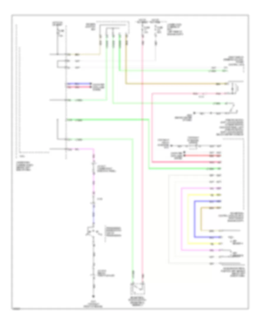
SHIFT INTERLOCK
Shift Interlock Wiring Diagram for Acura RDX 2014
List of elements for Shift Interlock Wiring Diagram for Acura RDX 2014:
- (right side of steering column) power control unit
- (top right front of engine) g101
- (top right of engine) j/c c013
- A19
- A20
- A28
- A29
- A34
- A35
- A36
- A37
- Accelerator pedal position (app) sensor (below left side of dash)
- App sensor a
- App sensor b
- Brake pedal position switch (brake pedal assembly)
- C114
- C139
- C16
- C31
- Computer data lines system
- D11
- D22
- Driver's junction box
- Fuse 10a
- Fuse 2-4 50a
- Fuse 7.5a
- G101 (top right front of engine)
- G503 (behind center of dash)
- Hot at all times
- Hot in on or start
- J/c c015 (below throttle inlet)
- J/c c017 (under right side cowl panel)
- Micu
- Park pin switch/ shift lock solenoid/ a/t gear position indicator panel light (park pin switch/ shift lock solenoid: below center console)
- Pnk
- Powertrain control module (pcm) (right side of engine compt)
- Red
- Transmission range switch (top of transmission)
- Under-dash fuse/relay box (behind left side of dash)
- Under-hood fuse/relay box (left rear of engine compt)
 English