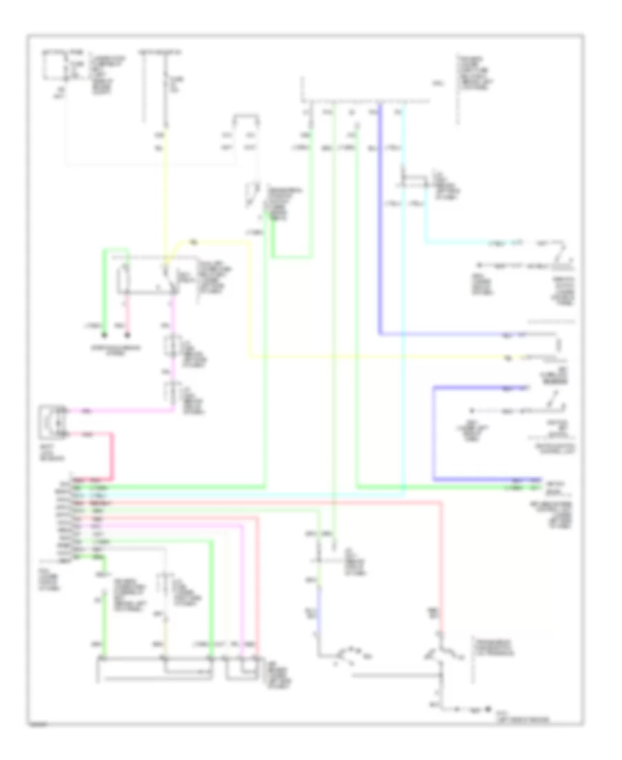
SHIFT INTERLOCK
Shift Interlock Wiring Diagram for Acura RL 2006
List of elements for Shift Interlock Wiring Diagram for Acura RL 2006:
- A11
- A13
- Acc relay
- App sensor (under left side of dash)
- Apsa
- Apsb
- Atp-n
- Atp-p
- Auxiliary under-dash relay box (under left side of dash)
- B-can
- B23
- Bksw
- Brake pedal position switch (near brake pedal)
- D13
- D14
- Driver's under- dash fuse/ relay box (behind left lick panel)
- Driver's under-dash fuse/relay box (behind left kick panel)
- E12
- E22
- Fuse 10a
- Fuse 15a
- G101 (left side of engine)
- G501 (under left side of dash)
- G503 (under middle of dash)
- Hot at all times
- Hot in acc or on
- Ignition key switch
- Ignition switch control unit
- J/c c507 (behind left side of dash)
- J/c c508 (behind left side of dash)
- J/c c517 (behind middle of dash)
- J/c c523 (behind middle of dash)
- J/c c525 (under right side of dash)
- Key interlock solenoid
- Key sw
- Keyless access control unit (under left side of dash)
- Micu
- N26
- N36
- P-pin
- P15
- P16
- Park pin switch (under console panel)
- Pcm (under middle of dash)
- Pnk
- Red
- Sg3
- Sg4
- Shift lock solenoid
- Sls
- Starting/charging system
- Transmission range switch (on transaxle)
- Under-hood fuse/relay box (left rear of engine compt)
- Vcc3
- Vcc4
- X10
- X18
 English