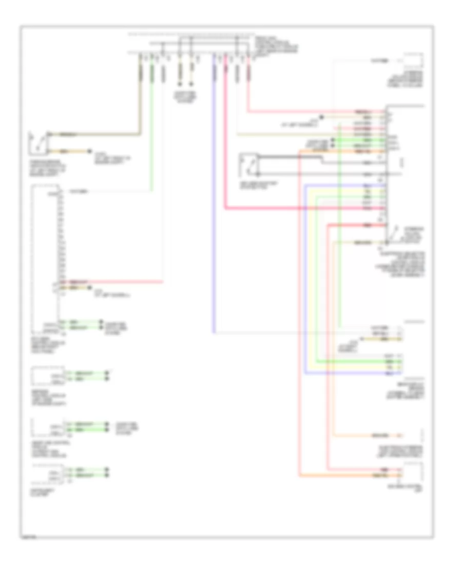
SHIFT INTERLOCK
Shift Interlock Wiring Diagram for Mercedes-Benz CLK350 2006
List of elements for Shift Interlock Wiring Diagram for Mercedes-Benz CLK350 2006:
- C10
- C22
- Can h
- Can l
- Can-ch
- Can-cl
- Computer data lines system
- Diag
- Eis (ezs) control unit
- Electronic selector lever module control module (under center console, at base of selector lever assembly)
- Electronic steering lock control module (left upper footwell)
- Esp/bas control module (left side of engine compt)
- Etc (egs) control module (behind right kick panel)
- Front sam control module fuse & relay module (left rear of engine compt)
- Gear display sensor (integral to gear shifter assembly)
- Instrument cluster
- Keyless go/start stop button
- Me-sfi (me) control module (in front sam control module)
- Nca
- Parking brake indicator switch (at left front of engine compt)
- Pnk
- Red
- Steering column lock ind switch
- Steering column module (behind steering wheel, in column)
- W16/3 (at left front of engine compt)
- W18 (at left doorsill)
- W19 (at right doorsill)
 English