
SHIFT INTERLOCK
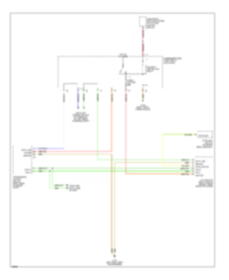
Shift Interlock Wiring Diagram for Mercedes-Benz E320 4Matic 2001
List of elements for Shift Interlock Wiring Diagram for Mercedes-Benz E320 4Matic 2001:
AIR CONDITIONINGANTI-LOCK BRAKESANTI-THEFTCOOLING FANBODY CONTROL MODULESCOMPUTER DATA LINESENGINE PERFORMANCEDEFOGGERSCRUISE CONTROLEXTERIOR LIGHTSGROUND DISTRIBUTIONHORNHEADLIGHTSNAVIGATIONINSTRUMENT CLUSTERPASSIVE RESTRAINTSPOWER DISTRIBUTIONMEMORY SYSTEMSPOWER TOP/SUNROOFINTERIOR LIGHTSPOWER MIRRORSPOWER DOOR LOCKSSHIFT INTERLOCKPOWER SEATSRADIOSTARTING/CHARGINGPOWER WINDOWSTRANSMISSIONTRUNK, TAILGATE, FUEL DOORSUPPLEMENTAL RESTRAINTSWIPER/WASHER