SHIFT INTERLOCK
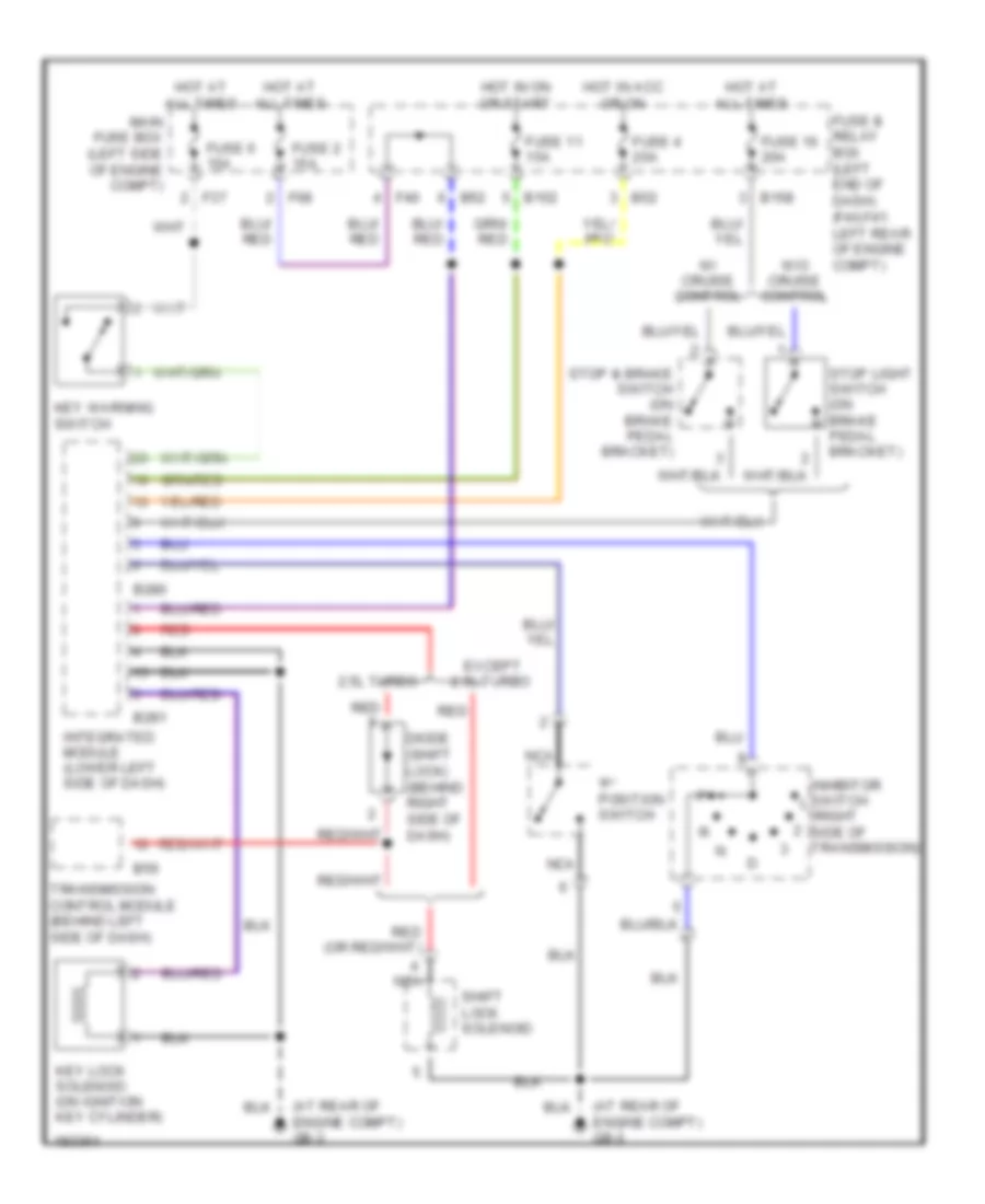
Shift Interlock Wiring Diagram for Subaru Outback 2004
List of elements for Shift Interlock Wiring Diagram for Subaru Outback 2004:
- "p" position switch
- (at rear of engine compt) gb-3
- (right side of transmission)
- 2.5l turbo
- B152
- B158
- B280
- B281
- B52
- B56
- Diode (shift lock) (behind right side of dash)
- Except 2.5l turbo
- F37
- F40
- F68
- Fuse & relay box (left end of dash) (f40,f41: left rear of engine compt)
- Fuse 11 15a
- Fuse 16 20a
- Fuse 2 15a
- Fuse 4 20a
- Fuse 6 15a
- Hot at all times
- Hot in acc or on
- Hot in on or start
- Inhibitor switch
- Integrated module (lower left side of dash)
- Key lock solenoid (on ignition key cylinder)
- Key warning switch
- Main fuse box (left side of engine compt)
- Nca
- Red
- Shift lock solenoid
- Stop & brake switch (on brake pedal bracket)
- Stop light switch (on brake pedal bracket)
- Transmission control module (behind left side of dash)
- W/ cruise control
- W/o cruise control
 English