
SHIFT INTERLOCKS
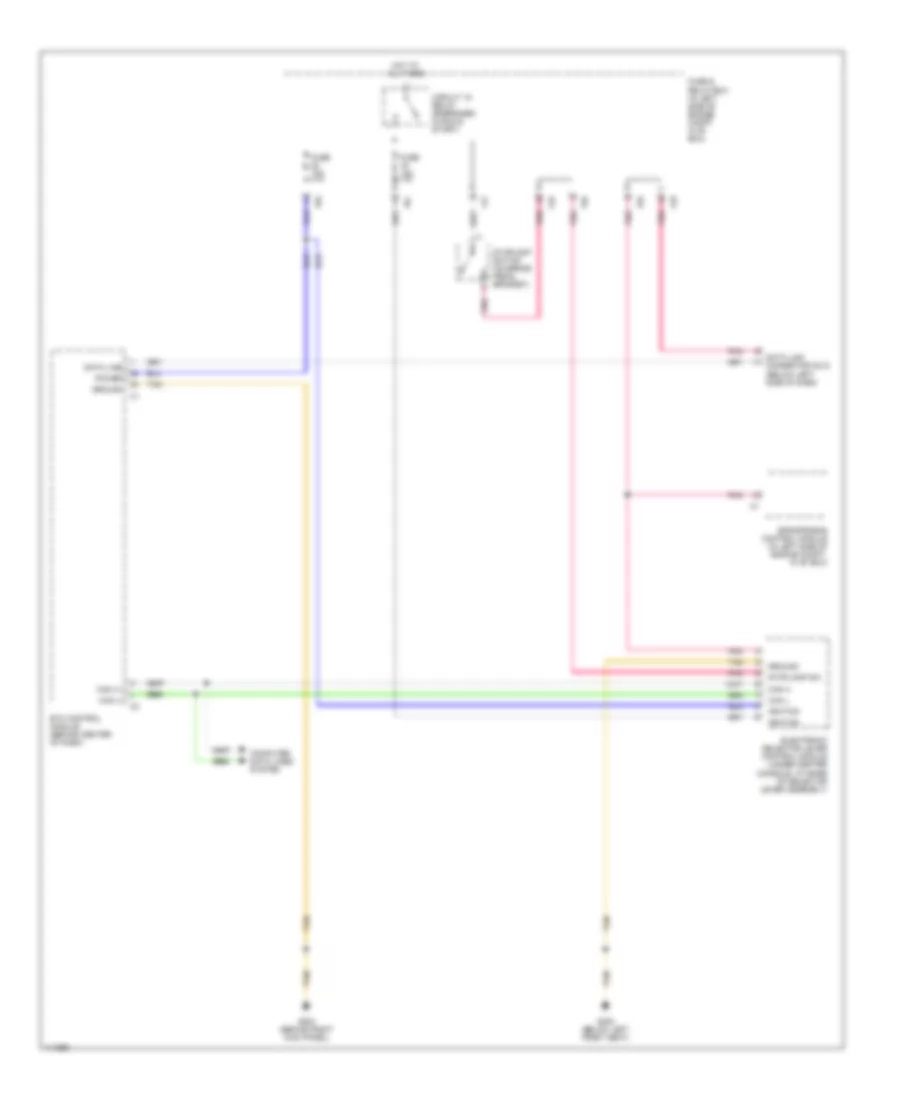
Shift Interlock Wiring Diagram for Mercedes-Benz ML430 2000
List of elements for Shift Interlock Wiring Diagram for Mercedes-Benz ML430 2000:
ANTI-LOCK BRAKESCOMPUTER DATA LINESCOOLING FANANTI-THEFTENGINE PERFORMANCEAIR CONDITIONINGBODY COMPUTERCRUISE CONTROLDEFOGGERSEXTERIOR LIGHTSHEADLIGHTSHORNPOWER DISTRIBUTIONINTERIOR LIGHTSPOWER MIRRORSGROUND DISTRIBUTIONINSTRUMENT CLUSTERMEMORY SYSTEMSPOWER WINDOWSPOWER DOOR LOCKSRADIOPOWER TOP/SUNROOFTRANSMISSIONSHIFT INTERLOCKSPOWER SEATSSTARTING/CHARGINGSUPPLEMENTAL RESTRAINTSWIPER/WASHER