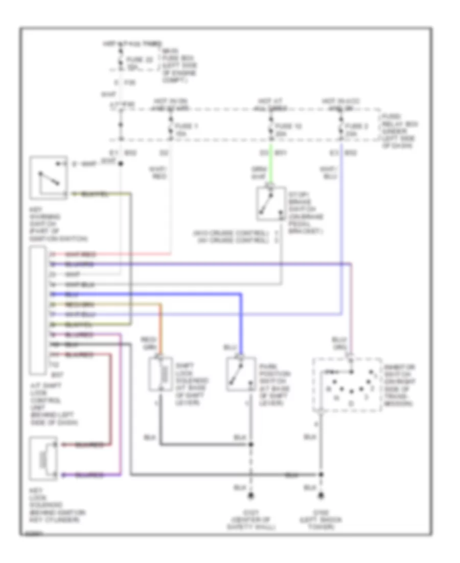
SHIFT INTERLOCKS
Shift Interlock Wiring Diagram for Subaru Impreza Brighton 1997
List of elements for Shift Interlock Wiring Diagram for Subaru Impreza Brighton 1997:
- (w/o cruise control) (w/ cruise control)
- A/t shift lock control unit (behind left side of dash)
- B51 d3
- B52 e3
- B57
- F35
- F40 a7
- Fuse 1 15a
- Fuse 12 20a
- Fuse 2 20a
- Fuse 22 15a
- Fuse/ relay box (under left side of dash)
- G102 (left shock tower)
- G121 (center of safety wall)
- Hot at all times
- Hot in acc and on
- Hot in on and start
- Inhbitor switch (on right side of trans- mission)
- Key lock solenoid (behind ignition key cylinder)
- Key warning switch (part of ignition switch)
- Main fuse box (left side of engine compt)
- Park position switch (at base of shift lever)
- Shift lock solenoid (at base of shift lever)
- Stop/ brake switch (on brake pedal bracket)
 English