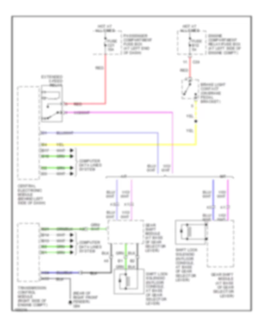
AUTOMOTIVE ELECTRICIANS PORTAL

SHIFT INTERLOCKS – Volvo S80 T-6 2002 – SYSTEM WIRING DIAGRAMS

SHIFT INTERLOCKS

Shift Interlock Wiring Diagram for Volvo S80 T-6 2002

Shift Interlock Wiring Diagram for Volvo S80 T-6 2002 https://portal-diagnostov.com/license.html
https://portal-diagnostov.com/license.html Automotive Electricians Portal FZCO Automotive Electricians Portal FZCO
Get access to all wiring diagrams of the carDownload PDF file

List of elements for Shift Interlock Wiring Diagram for Volvo S80 T-6 2002:

  • (in floor console, at base of gear selector lever)
  • (rear of right front fender) g94
  • A/t
  • A53
  • A54
  • B13
  • B14
  • B17
  • B18
  • B21
  • Brake light contact (on brake pedal bracket)
  • C24
  • Central electronic module (behind left side of dash)
  • Computer data lines system
  • Engine compartment relay/fuse box (at left side of engine compt)
  • Extended x-feed relay
  • Fuse b12 5a
  • Fuse c21 10a
  • Gear shift module (at base of gear selector lever)
  • Hot at all times
  • M/t
  • Passenger compartment fuse box (at left end of dash)
  • Red
  • Shift lock solenoid
  • Shift lock solenoid (in floor console, at base of gear selector lever)
  • Transmission control module (right side of engine compt)