STARTING/CHARGING
Charging Wiring Diagram for Chevrolet Uplander LS 2007

List of elements for Charging Wiring Diagram for Chevrolet Uplander LS 2007:
- Battery
- Battery current sensor (right front of engine compt, near battery)
- Battery ind
- Battery saver active charging system failure
- Body control module (bcm) (below left side of dash, left of steering column)
- Class 2 serial data
- Clstr/ hvac fuse 8 10a
- Current sens sig
- Current sense
- Engine control module (ecm) (in air cleaner assembly)
- G102 (right side of engine compt on frame rail, right of engine fuse block)
- G115 (at engine to transmission stud nearest starter below g113)
- Gen field duty cycle sign
- Gen turn on sig
- Generator
- Ground
- Hot at all times
- I/p dimming voltage ref
- I/p fuse block (right side of dash, behind access panel)
- Ign
- Ign 1 volt
- Instrument panel cluster
- Interior lights system
- Logic
- Low ref
- Messege center
- Power distribution system
- Red
- S257 (in dash harness, 8.5 cm from breakout for ipc toward right side of dash)
- Sp205 (on dash harness near headlamp switch connector, behind left dash access panel)
- Starter motor
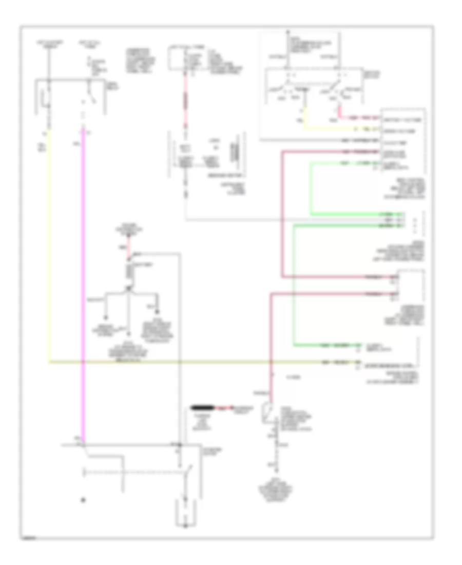
Starting Wiring Diagram for Chevrolet Uplander LS 2007
List of elements for Starting Wiring Diagram for Chevrolet Uplander LS 2007:
- 12-volt ref
- Acc
- Batt volt
- Battery
- Body control module (bcm) (below left side of dash, left of steering column)
- Charging circuit
- Class 2 serial data
- Clstr/ hvac fuse 8 10a
- Crank voltage
- Crnk relay
- Disable starting
- Engine control module (ecm) (in air cleaner assembly)
- G101 (left side of engine compt, on upper front of radiator support)
- G102 (right side of engine compt on frame rail, right of engine fuse block)
- G115 (at engine to transmission stud nearest starter, below g113)
- Ground distribution system
- Hood ajar switch (upper center of radiator support, on hood latch)
- Hood ajar switch sig
- Hot at all times
- Hot in start or run
- I/p fuse block (right side of dash, behind access panel)
- Ignition 1 voltage
- Ignition switch
- Instrument panel cluster
- Lock
- Logic
- Message center
- Pnk
- Power distribution system
- Red
- Run
- S103
- S279 (in steering column harness, 20 cm from c201)
- Sp205 (on dash harness near headlamp switch connector, behind left dash access panel)
- Start
- Start enable rly ctrl
- Starter motor
- Strtr sol fuse 30 40a
- Underhood fuse block (in underhood compt, above right front wheel well)
- W/ rke