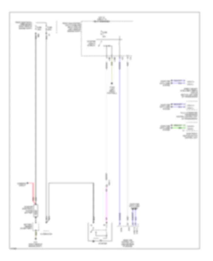
STARTING/CHARGING
Charging Wiring Diagram for Mercedes-Benz CLS550 4Matic 2013

List of elements for Charging Wiring Diagram for Mercedes-Benz CLS550 4Matic 2013:
- (left front footwell) w15/5
- (right side of trunk) eco start/stop function additional battery relay
- (right side of trunk) rear sam control unit w/ fuse & relay module
- Additional battery circuit 30 fuse
- Alternator
- Battery sensor (on battery)
- C19i
- C5c
- C7i
- Can b h
- Can b l
- Can e h
- Can e l
- Computer data lines system
- Display
- Eco start/stop function additional battery
- Eco start/stop function button
- Front electrical prefuse box (right rear of engine compt)
- Front sam control unit w/ fuse and relay module (left rear of engine compt)
- Fuse 100a
- Fuse 150a
- Fuse 400a
- Fuse 7.5a
- Hot at all times
- Instrument cluster
- Lin
- Lin c1
- Me-sfi (me) control unit (center rear of engine)
- Mr8
- Nca
- On-board electrical system battery
- Rear sam control unit w/ fuse & relay module (right side of trunk)
- Rear sam control unit w/ fuse and relay module circuit 30 fuse
- Red
- Starter
- Terminal block (circuit 30)
- W10 (right rear of engine compt)
- W7/6
Starting Wiring Diagram for Mercedes-Benz CLS550 4Matic 2013
List of elements for Starting Wiring Diagram for Mercedes-Benz CLS550 4Matic 2013:
- Alternator
- Battery sensor (on battery)
- C15m
- C3m
- C4i
- C6i
- Can c h
- Can c l
- Can e h
- Can e l
- Charging circuit
- Computer data lines system
- Direct select intelligent servo module (bottom left side of transmission)
- Electronic ignition switch control unit
- Front electrical prefuse box (right rear of engine compt)
- Front sam control unit w/ fuse and relay module (left rear of engine compt)
- Fully integrated transmission control control unit (in transmission)
- Fuse 150a
- Fuse 20a
- Fuse 400a
- Hot w/ circuit 15 relay energized
- Me-sfi (me) control unit (center rear of engine)
- Mr8
- Nca
- On board electrical system battery
- Red
- Starter
- Starter circuit 50 relay
- Str
- Str+
- W10 (right rear of engine compt)
- W15/5 (left front footwell)
- X26-c1