STARTING/CHARGING
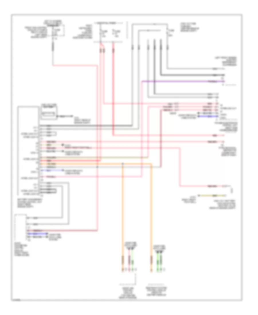
Battery Management System Wiring Diagram for Mercedes-Benz S400 2013
List of elements for Battery Management System Wiring Diagram for Mercedes-Benz S400 2013:
- (+)
- (left front engine) electric refrigerant compressor
- Battery management system control unit (right rear engine compt)
- Can-i h
- Can-i l
- Canih
- Canil
- Computer data lines system
- Contactor
- Dc/dc converter control module (right front wheelhouse)
- Front sam control module w/ fuse & relay module (left rear engine compt)
- Fuse 10a
- Fuse 15a
- Fuse 5a
- Fuse 60a
- High volt battery cooling system shutoff valve (rear of engine compt)
- High voltage battery
- High voltage fuse box (center rear of engine compt)
- Hot at all times
- Hot w/ chassis circuit 87 relay energized
- Hv +
- Hv -
- Inter lock in
- Inter lock out
- Interlock out
- Me-sfi (me) control module (top center rear of engine)
- Nca
- Power electronics control unit (right side undercarriage)
- Pyrotechnical separator (under right side of dash)
- Red
- Restraint system control module (front of center console)
- Right instrument panel fuse box (under right side dash cover)
- W10 (right rear of engine compt)
- W15/1 (right front footwell)
- X26/29
 English