STARTING/CHARGING
Charging Wiring Diagram, with Start-Stop System for Volvo S60 T5 2014

List of elements for Charging Wiring Diagram, with Start-Stop System for Volvo S60 T5 2014:
- (left front of engine compt) gxx10
- 74/316
- A38
- A39
- A92
- Air conditioning system
- Alternator control module (acm)
- B41
- B54
- Battery
- Battery fuse
- Battery monitoring sensor (on battery)
- Battery relay
- Central electronic module
- Central electronic module (right end of dash)
- Computer data lines system
- Driver information module (dim)
- Engine compartment cold zone (center rear of engine compt)
- Engine compartment distribution box (left side of engine compt)
- Engine control module (left rear of engine compt)
- Fuse 15a
- Fuse 70a
- Fuse b33 5a
- Fuse mf2 175a
- Fuse pf1 150a
- Fuse pf4 150a
- G131
- G3 (left side of engine compt)
- Hot w/ engine management system main relay energized
- Nca
- Red
- Secondary battery
- Secondary battery relay
- Starting circuit
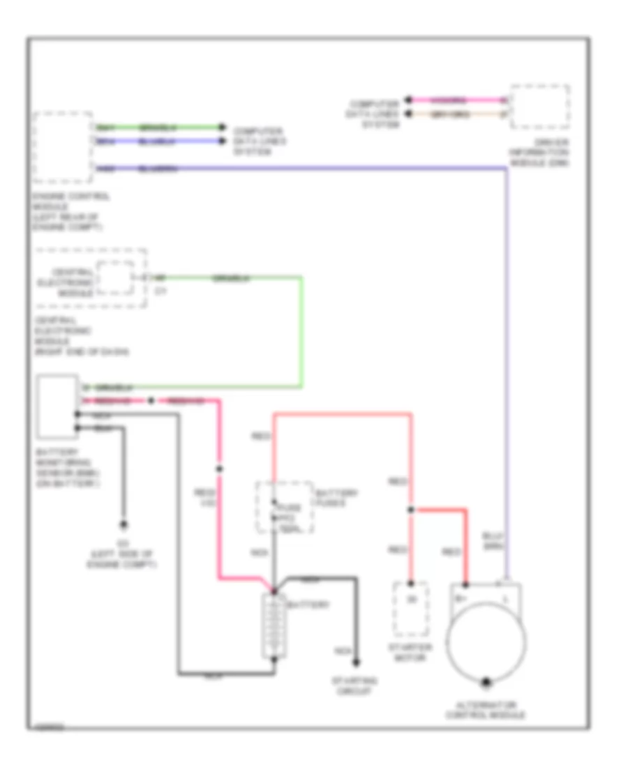
Charging Wiring Diagram, without Start-Stop System for Volvo S60 T5 2014
List of elements for Charging Wiring Diagram, without Start-Stop System for Volvo S60 T5 2014:
- A92
- Alternator control module
- B41
- B54
- Battery
- Battery fuses
- Battery monitoring sensor (bms) (on battery)
- Central electronic module
- Central electronic module (right end of dash)
- Computer data lines system
- Driver information module (dim)
- Engine control module (left rear of engine compt)
- Fuse pf2 150a
- G3 (left side of engine compt)
- Nca
- Red
- Starter motor
- Starting circuit
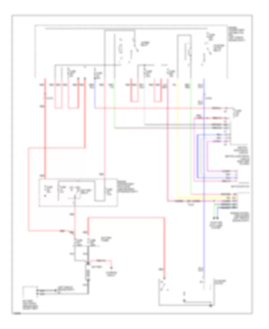
Starting Wiring Diagram, with Start-Stop System for Volvo S60 T5 2014
List of elements for Starting Wiring Diagram, with Start-Stop System for Volvo S60 T5 2014:
- (left side of engine compt) g3
- 15-feed relay
- 74/301
- 74/302
- 74/316
- B11
- B15
- B41
- B54
- Battery
- Battery fuses
- Battery monitoring sensor (bms) (on battery)
- Battery relay
- Central electronic module
- Central electronic module (right end of dash)
- Charging circuit
- Computer data lines system
- Engine compartment cold zone (center rear of engine compt)
- Engine compartment distribution box (left side of engine compt)
- Engine control module (ecm) (left rear of engine compt)
- Fuse a2 50a
- Fuse a9 30a
- Fuse b17 20a
- Fuse b20 10a
- Fuse b27 5a
- Fuse b34 30a
- Fuse f24 5a
- Fuse mf1 175a
- Fuse n/a
- Fuse pf1 150a
- Fuse pf2 150a
- Ignition switch
- Nca
- Red
- Starter motor
- Starter motor relay
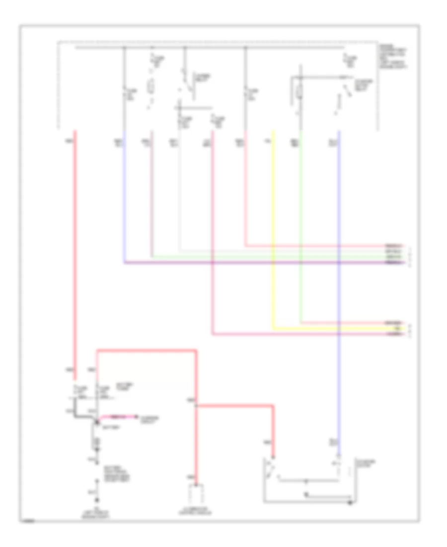
Starting Wiring Diagram, without Start-Stop System (1 of 2) for Volvo S60 T5 2014
List of elements for Starting Wiring Diagram, without Start-Stop System (1 of 2) for Volvo S60 T5 2014:
- 15-feed relay
- Alternator control module
- Battery
- Battery fuses
- Battery monitoring sensor (bms) (on battery)
- Charging circuit
- Engine compartment distribution box (left side of engine compt)
- Fuse a1 50a
- Fuse a2 50a
- Fuse b17 20a
- Fuse b20 10a
- Fuse b27 5a
- Fuse b34 30a
- Fuse pf1 150a
- Fuse pf2 150a
- G3 (left side of engine compt)
- Nca
- Red
- Starter motor
- Starter motor relay
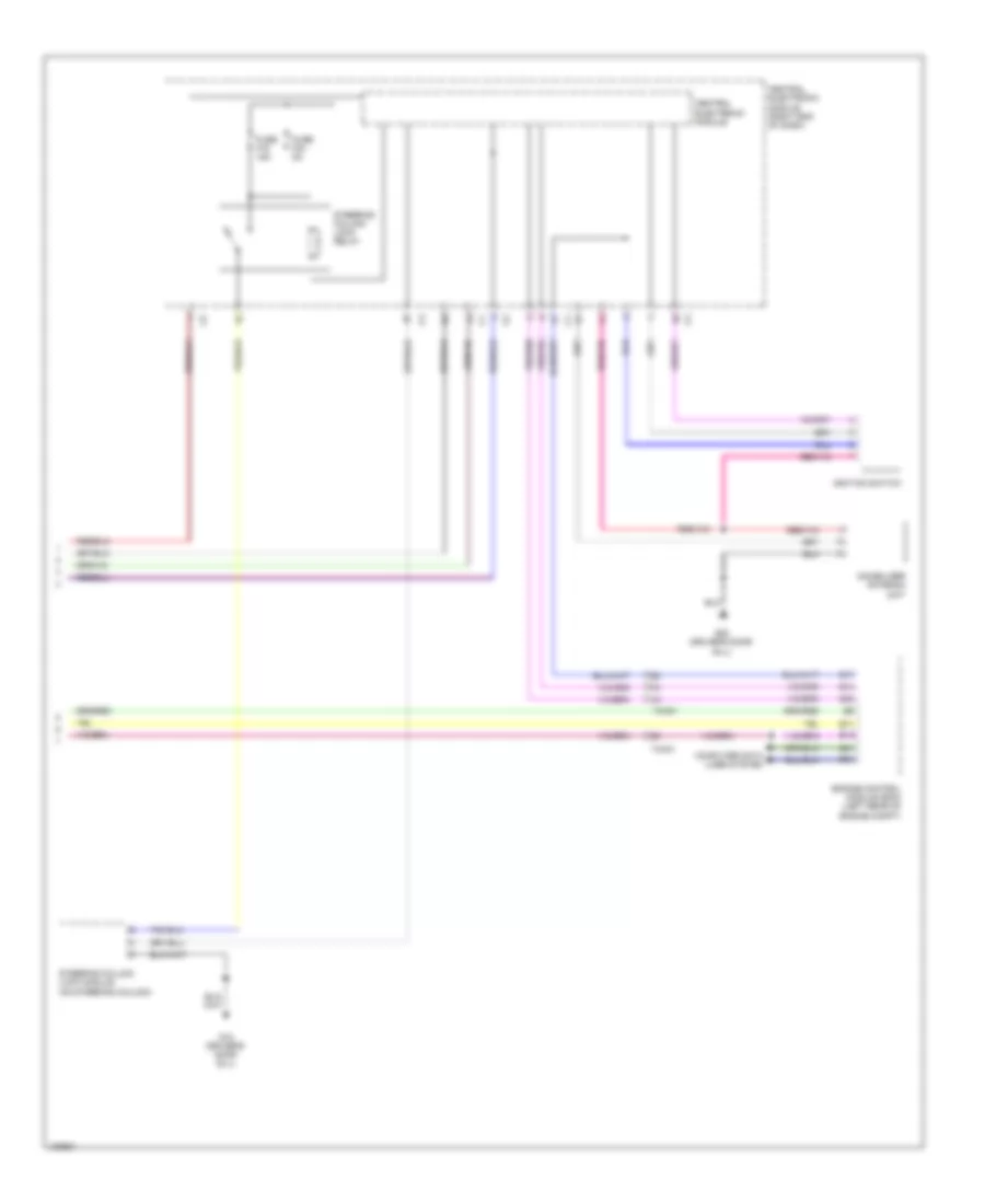
Starting Wiring Diagram, without Start-Stop System (2 of 2) for Volvo S60 T5 2014
List of elements for Starting Wiring Diagram, without Start-Stop System (2 of 2) for Volvo S60 T5 2014:
- 74/301
- B11
- B14
- B15
- B17
- B30
- B41
- B54
- Central electronic module
- Central electronic module (right end of dash)
- Computer data lines system
- Engine control module (ecm) (left rear of engine compt)
- Fuse f15 15a
- Fuse f24 5a
- G10 (driver's door sill)
- G83 (driver's door sill)
- Ignition switch
- Immobilizer antenna unit
- Steering column lock module (on steering column)
- Steering column lock relay