STARTING/CHARGING
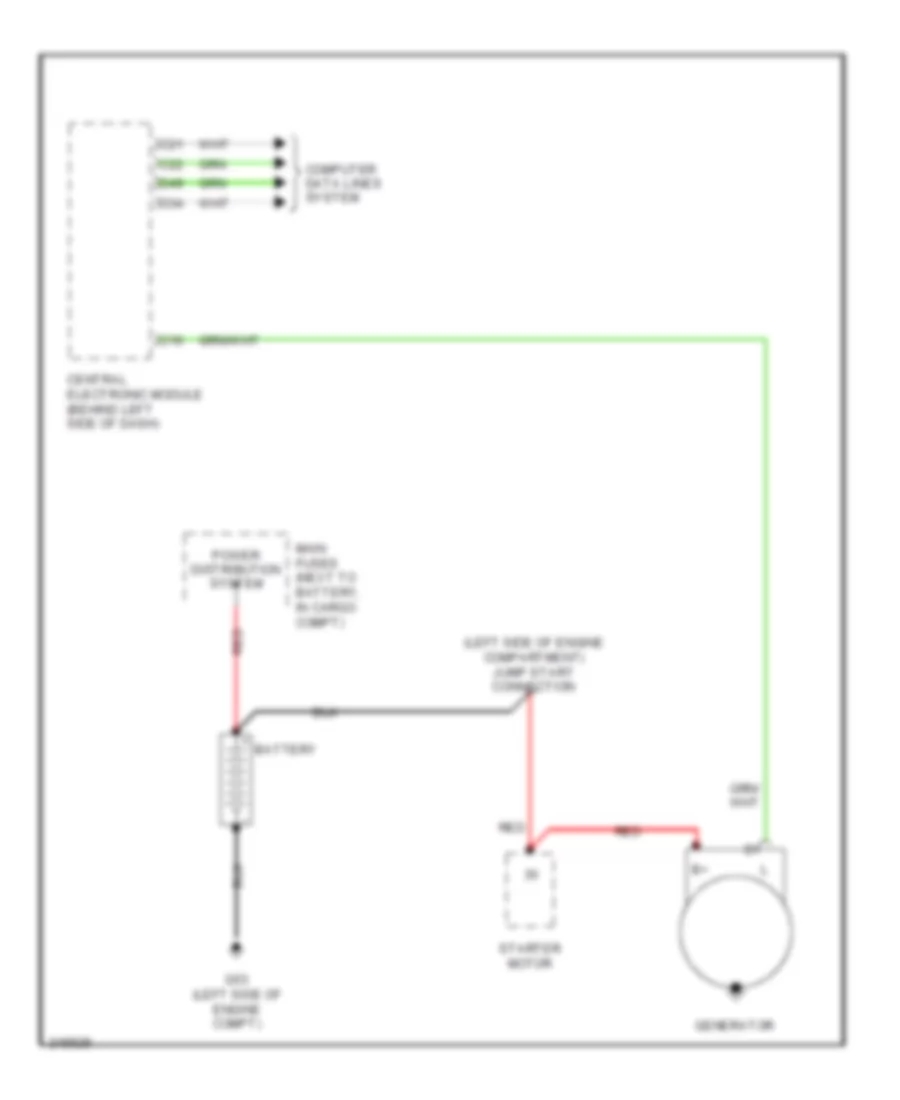
Charging Wiring Diagram, Early Production for Volvo XC90 2005

List of elements for Charging Wiring Diagram, Early Production for Volvo XC90 2005:
- (left side of engine compartment) auxiliary start connection
- Battery
- C16
- C21
- C22
- Central electronic module (behind left side of dash)
- Computer data lines system
- D34
- D49
- Engine compartment relay/fuse box (at left side of engine compartment, forward of strut tower)
- G53 (left side of engine compt)
- Generator
- Instrument cluster
- Main fuses (next to battery, in cargo compt)
- Power distribution system
- Red
- Starter motor
Charging Wiring Diagram, Late Production for Volvo XC90 2005
List of elements for Charging Wiring Diagram, Late Production for Volvo XC90 2005:
- (left side of engine compartment) jump start connection
- Battery
- C16
- C21
- C22
- Central electronic module (behind left side of dash)
- Computer data lines system
- D34
- D49
- G53 (left side of engine compt)
- Generator
- Main fuses (next to battery, in cargo compt)
- Power distribution system
- Red
- Starter motor
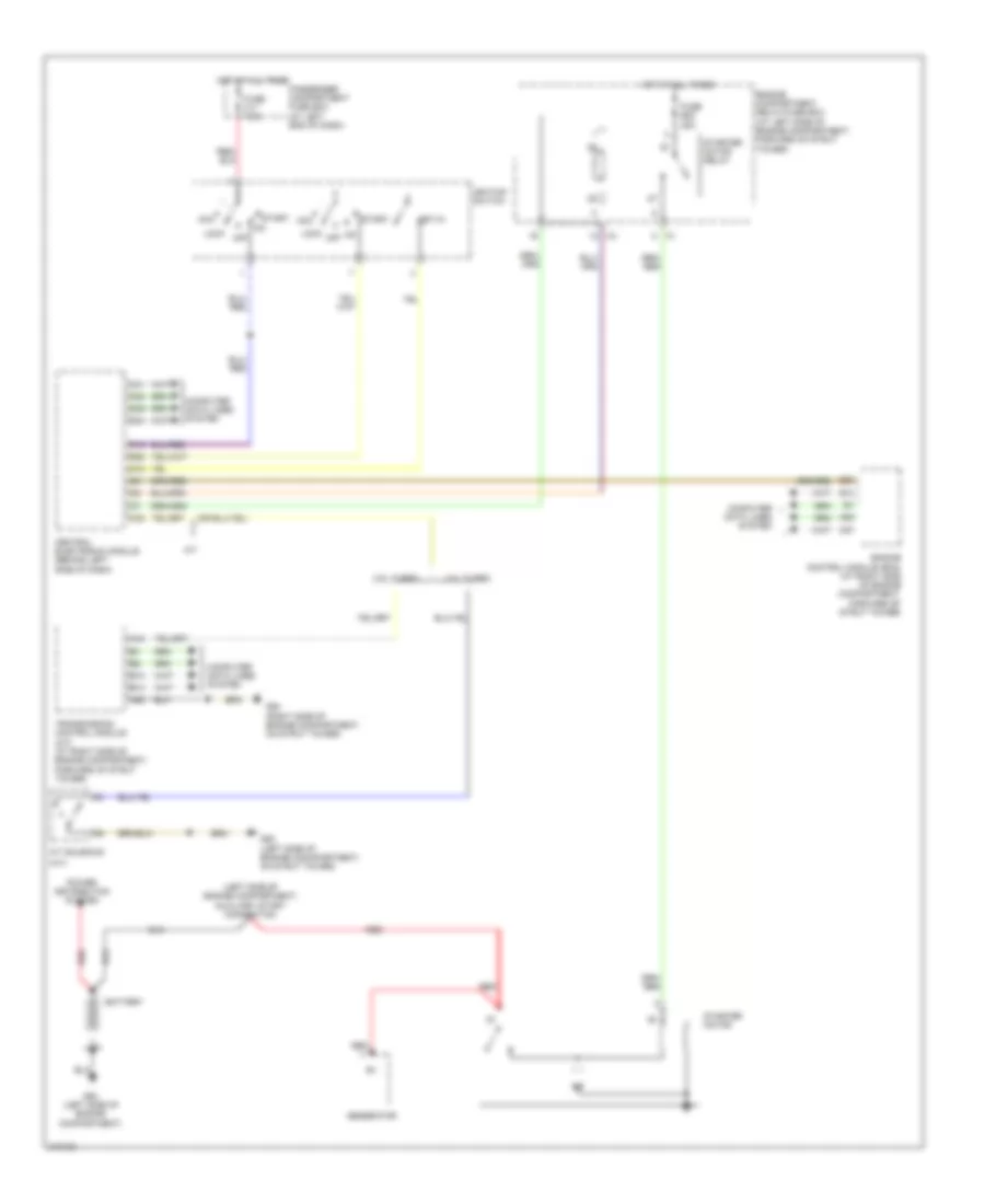
Starting Wiring Diagram, Early Production for Volvo XC90 2005
List of elements for Starting Wiring Diagram, Early Production for Volvo XC90 2005:
- (a/t)
- (left side of engine compartment) auxiliary start connection
- 2.5l turbo
- 2.9l turbo
- A/t
- A/t solenoid
- A37
- A44
- A53
- A55
- Acc
- B13
- B14
- B23
- Battery
- C21
- C22
- C28
- Central electronic module (behind left side of dash)
- Computer data lines system
- D15
- D16
- D34
- D49
- D60
- Engine compartment relay/fuse box (at left side of engine compartment, forward of strut tower)
- Engine control module (ecm) (at right side of engine compartment, forward of strut tower)
- Fuse b22 35a
- Fuse c11 7.5a
- G53 (left side of engine compartment)
- G93 (left side of engine comapartment, on strut tower)
- G94 (right side of engine compartment, on strut tower)
- Generator
- Hot at all times
- Ignition switch
- Key-in
- Lock
- Off
- Passenger compartment fuse box (at left end of dash)
- Power distribution system
- Red
- Start
- Starter motor
- Starter motor relay
- Transmission control module (a/t) (at right side of engine compartment, forward of strut tower)
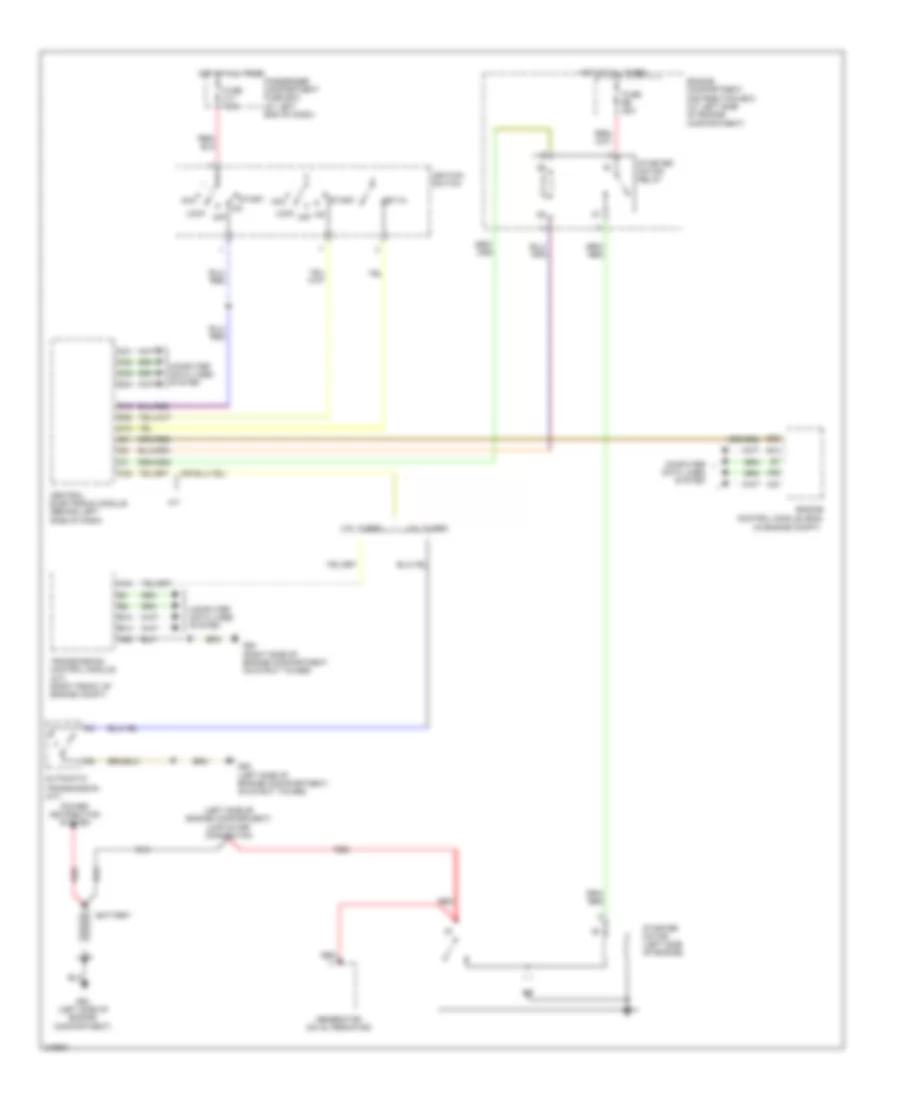
Starting Wiring Diagram, Late Production for Volvo XC90 2005
List of elements for Starting Wiring Diagram, Late Production for Volvo XC90 2005:
- (in engine compt)
- (left side of engine compartment) jump start connection
- 2.5l turbo
- 2.9l turbo
- A/t
- A37
- A44
- A53
- A55
- Acc
- Automatic
- B13
- B14
- B23
- Battery
- C21
- C22
- C28
- Central electronic module (behind left side of dash)
- Computer data lines system
- D15
- D16
- D34
- D49
- D60
- Engine compartment distribution box (at left side of engine compartment)
- Engine control module (ecm)
- Fuse b6 25a
- Fuse c11 7.5a
- G53 (left side of engine compartment)
- G93 (left side of engine comapartment, on strut tower)
- G94 (right side of engine compartment, on strut tower)
- Generator (on alternator)
- Hot at all times
- Ignition switch
- Key-in
- Lock
- Off
- Passenger compartment fuse box (at left end of dash)
- Power distribution system
- Red
- Start
- Starter motor (left side of engine)
- Starter motor relay
- Transmission (a/t)
- Transmission control module (a/t) (right front of engine compt)