SUPPLEMENTAL RESTRAINTS
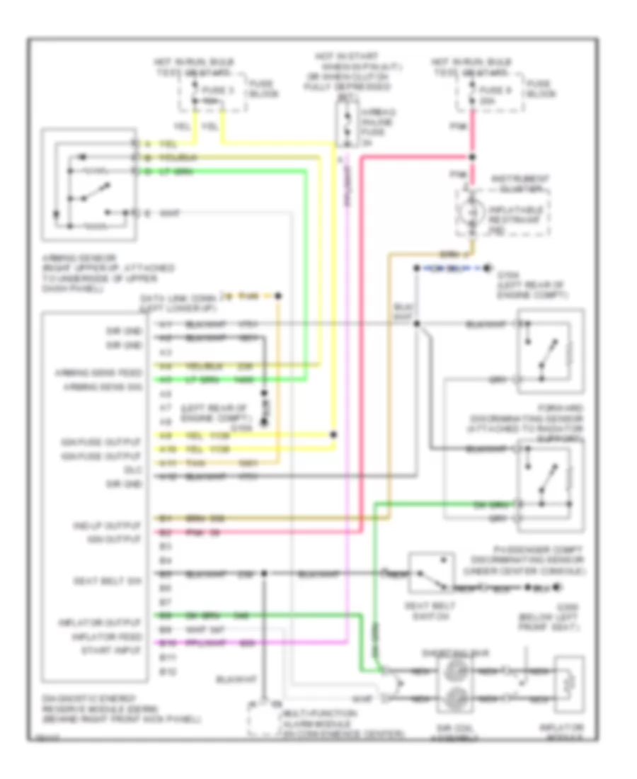
Supplemental Restraint Wiring Diagram for Chevrolet Beretta Z26 1996
List of elements for Supplemental Restraint Wiring Diagram for Chevrolet Beretta Z26 1996:
- (left rear of engine compt)
- A nca
- A10
- A11
- A12
- Airbag in-line fuse 3a
- Arming sens feed
- Arming sens sig
- Arming sensor (right upper i/p, attached to underside of upper dash panel)
- B10
- B11
- B12
- Data link conn (left lower i/p)
- Diagnostic energy reserve module (derm) (behind right front kick panel)
- Dlc
- Forward discriminating sensor (attached to radiator support)
- Fuse 3 10a
- Fuse 9 20a
- Fuse block
- G104
- G104 (left rear of engine compt)
- G300 (below left front seat)
- Hot in run, bulb test or start
- Hot in start
- Ign fuse output
- Ign output
- Ind lp output
- Inflatable restraint ind
- Inflator feed
- Inflator module
- Inflator output
- Instrument cluster
- Multi-function alarm module (in convenience center)
- Nca
- Or when clutch fully depressed (m/t)
- Passenger compt discriminating sensor (under center console)
- Pnk
- Seat belt sw
- Seat belt switch
- Shorting bar
- Sir coil assembly
- Sir gnd
- Start input
- Tan
- When in p/n (a/t)
 English