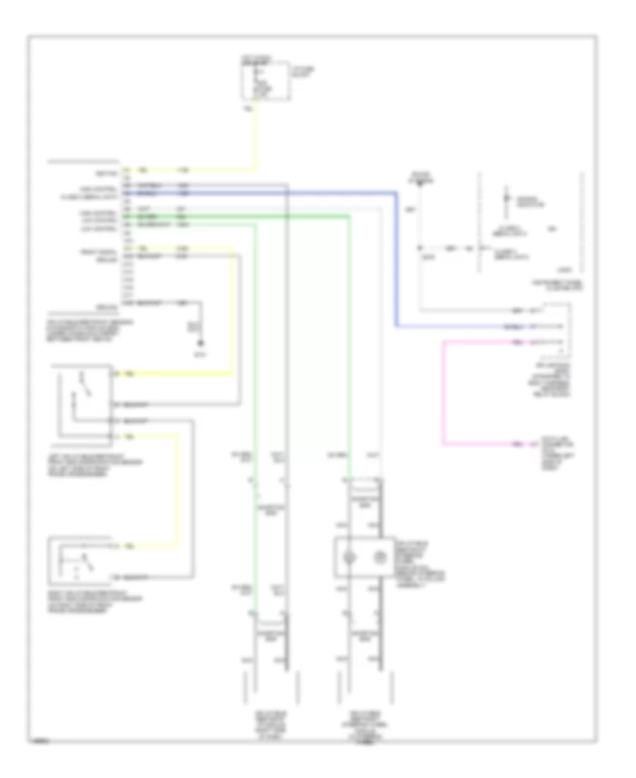
SUPPLEMENTAL RESTRAINTS
Supplemental Restraints Wiring Diagram for Chevrolet Blazer 2005
List of elements for Supplemental Restraints Wiring Diagram for Chevrolet Blazer 2005:
- A10
- A11
- A12
- A13
- A14
- A15
- A16
- A17
- A18
- Air bag indicator
- Class 2 serial data
- Data link connector (dlc) (under left side of dash)
- Front signal
- G101
- Ground
- High control
- Hot in run or start
- I/p fuse block
- Ign
- Ignition
- Inflatable restraint i/p module (right side of dash)
- Inflatable restraint sensing & diagnostic module (sdm) (under console & carpet, between front seats)
- Inflatable restraint steering wheel module (in steering wheel)
- Inflatable restraint steering wheel module coil (behind steering wheel, in column assembly)
- Instrument panel cluster (ipc)
- Left inflatable restraint front end discriminating sensor (on left side of front frame crossmember)
- Logic
- Low control
- Nca
- Right inflatable restraint front end discriminating sensor (on right side of front frame crossmember)
- S276
- Shorting bar
- Sir fuse 15a
- Sound systems
- Splice pack sp201 (strapped to body harness, near body relay block)
 English