SUPPLEMENTAL RESTRAINTS
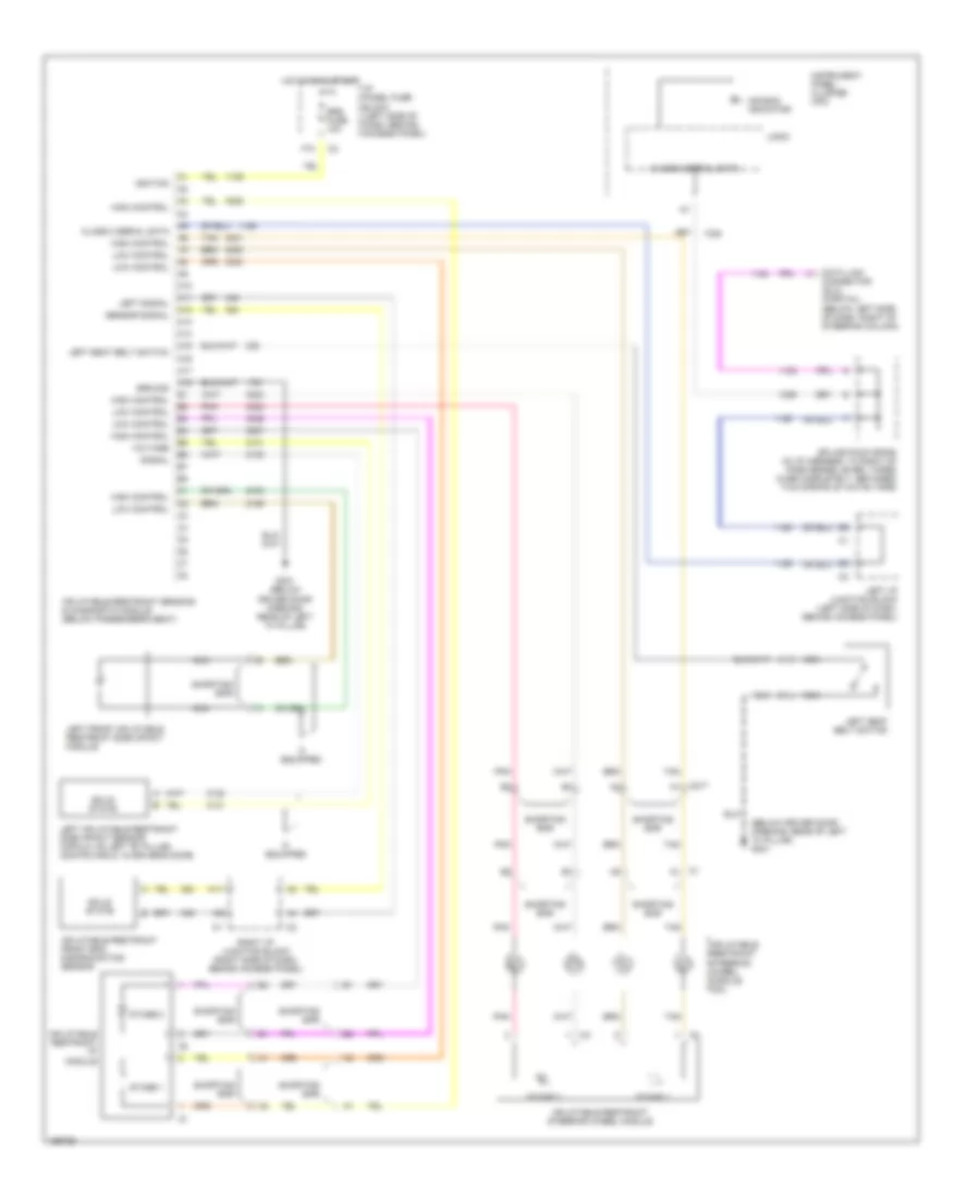
Supplemental Restraints Wiring Diagram for Chevrolet Impala 2003
List of elements for Supplemental Restraints Wiring Diagram for Chevrolet Impala 2003:
- (below driver door opening, rear of left "a" pillar) g301
- A10
- A11
- A12
- A13
- A14
- A15
- A16
- A17
- A18
- Air bag indicator
- C1 a1
- C217 a1
- Class 2 serial data
- Data link connector (dlc) (partial) (below left side of dash, right of steering column)
- F10
- G301 (below driver door opening, rear of left "a" pillar)
- Ground
- High control
- Hot in on & start
- I/p panel fuse block (left side of dash, behind access panel)
- If equipped
- Ignition
- Inflatable restraint front end discriminating sensor
- Inflatable restraint i/p module
- Inflatable restraint sensing & diagnostic module (below passenger's seat)
- Inflatable restraint steering wheel module
- Inflatable restraint steering wheel module coil
- Instrument panel cluster (ipc)
- Left front inflatable restraint side impact module
- Left i/p junction block (left side of dash, behind access panel)
- Left inflatable restraint side impact sensor (impala: on left "b" pillar) (monte carlo: in driver's door)
- Left seat belt switch
- Left signal
- Logic
- Low control
- Nca
- Pnk
- Right i/p junction block (right side of dash, behind access panel)
- Sensor signal
- Shorting bar
- Signal
- Solid state
- Splice pack sp205 (in i/p harness, to right of park brake lever, taped over completely, between two strips of white tape)
- Srs fuse 10a
- Stage 1
- Stage 2
- Tan
- Voltage
 English