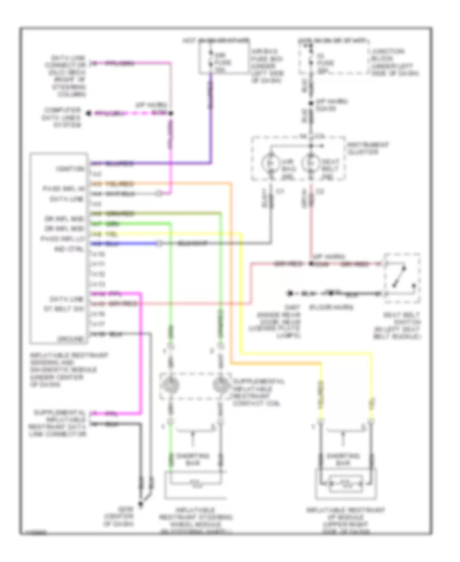
SUPPLEMENTAL RESTRAINTS
Supplemental Restraint Wiring Diagram for Chevrolet Tracker 1999
List of elements for Supplemental Restraint Wiring Diagram for Chevrolet Tracker 1999:
- (floor harn)
- (i/p harn) s249
- (i/p harn) s260
- A10
- A11
- A12
- A13
- A14
- A15
- A16
- A17
- A18
- Air bag fuse box (under left side of dash)
- Air bag ind
- Computer data lines system
- Data line
- Data link connector (dlc) obd-ii (right of steering column)
- Dr infl mod
- G206 (center of dash)
- G407 (inside rear door, near license plate lamps)
- Ground
- Hot in on or start
- Ig fuse 20a
- Ignition
- Ind ctrl
- Inflatable restraint data link connector
- Inflatable restraint i/p module (upper right side of dash)
- Inflatable restraint sensing and diagnostic module (under center of dash)
- Inflatable restraint steering wheel module (in steering wheel)
- Instrument cluster
- Junction block (under left side of dash)
- Nca
- Pass infl hi
- Pass infl lo
- S300
- Seat belt ind
- Seat belt switch (in left seat belt buckle)
- Shorting bar
- Sir fuse 15a
- St belt sw
 English