SUPPLEMENTAL RESTRAINTS
Supplemental Restraint Wiring Diagram (1 of 2) for Volvo S80 T-6 2000

List of elements for Supplemental Restraint Wiring Diagram (1 of 2) for Volvo S80 T-6 2000:
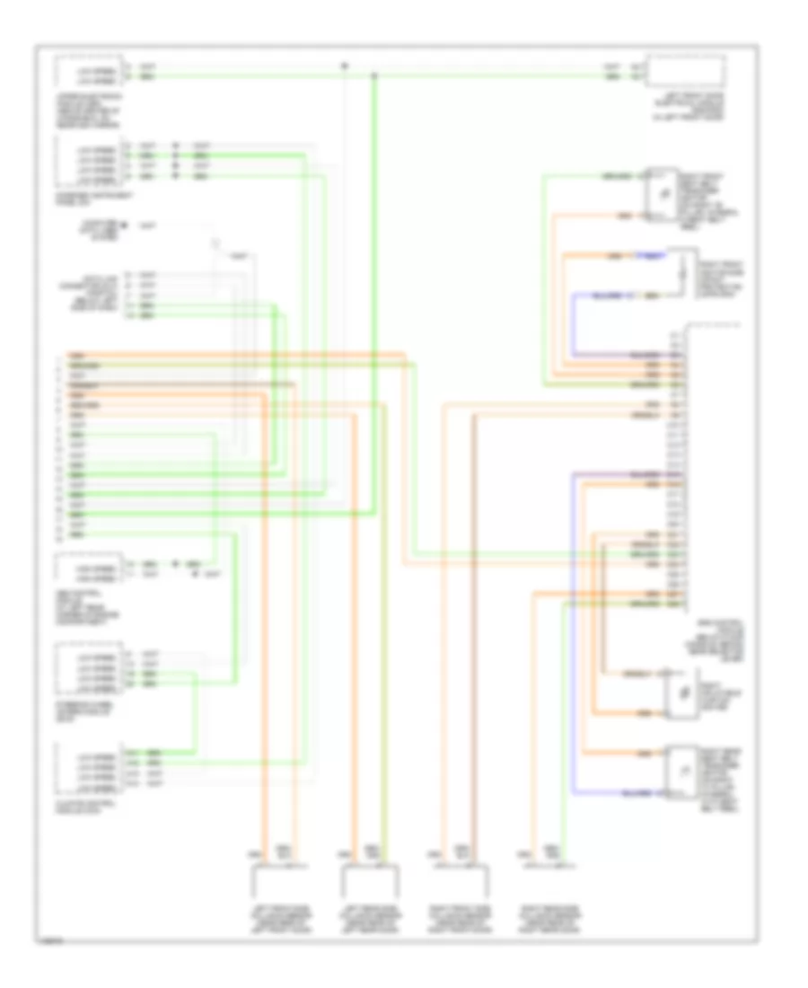
Supplemental Restraint Wiring Diagram (2 of 2) for Volvo S80 T-6 2000
List of elements for Supplemental Restraint Wiring Diagram (2 of 2) for Volvo S80 T-6 2000: