TRANSMISSION
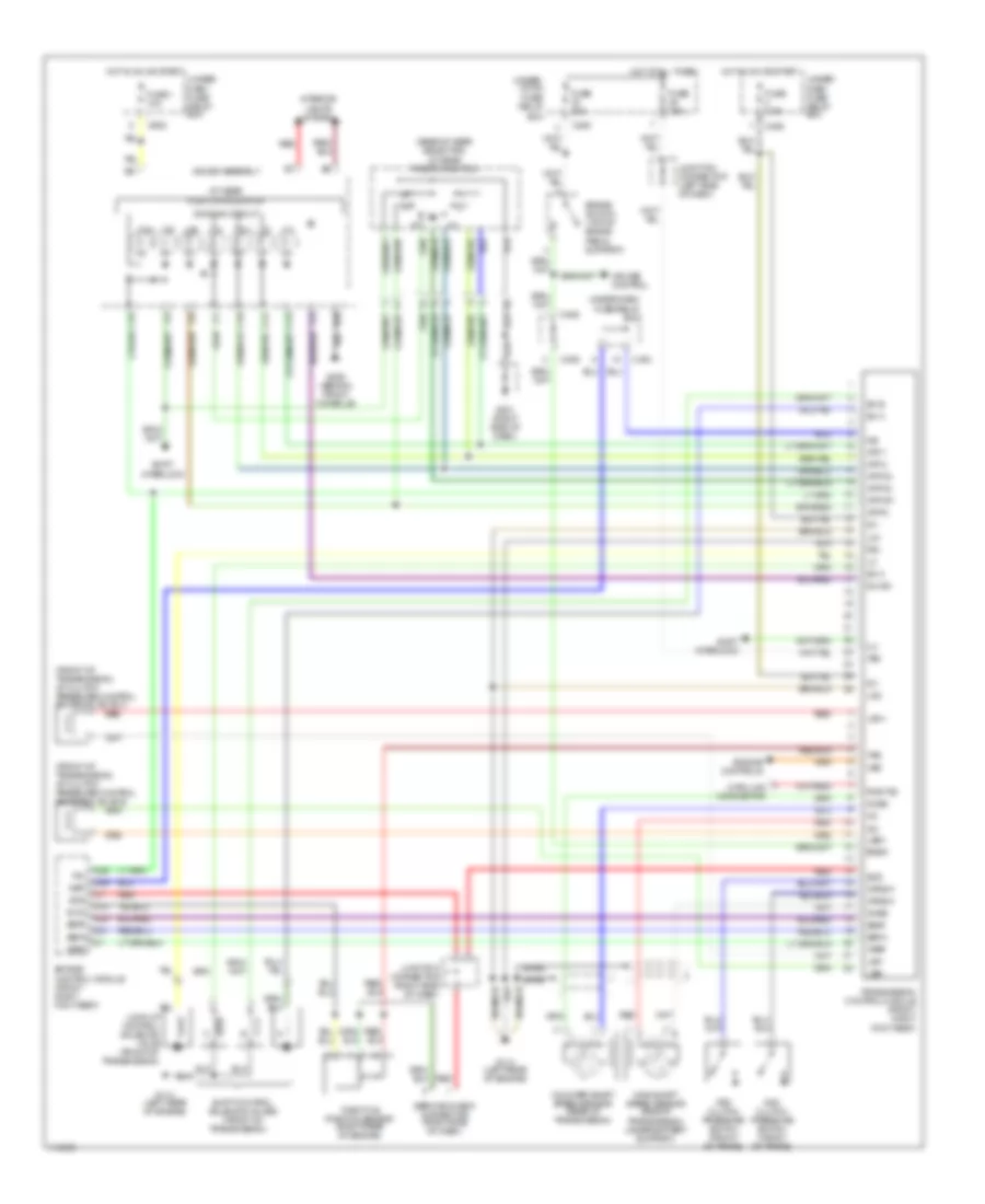
A/T Wiring Diagram for Acura 3.0CL 1997
List of elements for A/T Wiring Diagram for Acura 3.0CL 1997:
- (base of gear selector) a/t gear position switch
- (front of transmission) a/t clutch pressure control solenoid valve a
- (front of transmission) a/t clutch pressure control solenoid valve b
- 2nd clutch pressure switch (front of trans)
- 3rd clutch pressure switch (front of trans)
- A/t gear position indicator
- Atp 1
- Atp 2
- Atp d3
- Atp d4
- Atp np
- Atp r
- B10
- Bksw
- Box
- Braid
- Brake switch (top of brake pedal support)
- C13
- C14
- C15
- C16
- C253
- C26
- C29
- C30
- C31
- C403
- C406
- C602
- Counter-shaft speed sensor (rear of transmission)
- Cruise control
- D10
- D4 ind
- Data link connector
- Dimming circuit
- Engine control module (front right foot rest)
- Engine controls
- Fuse 1 10a
- Fuse 20a
- Fuse 7.5a
- G114 (left rear of engine)
- G201 (right side of dash)
- G206 (behind front console)
- Gauge assembly
- Hot at all times
- Hot in on or start
- Ig1
- Ilu
- Interior lights system
- Junction connector (left side of dash)
- Junction connector (right side of dash)
- Lg1
- Lg2
- Lock-up control solenoid valve (front of transmission)
- Lsa +
- Lsa -
- Lsb +
- Lsb -
- Main-shaft speed sensor (side of transmission, under battery support)
- Ncsg
- Nep
- Nmsg
- Op2sw
- Op3sw
- P/n
- Pg1
- Red
- Rxd/txd
- Scs
- Seaf
- Sefa
- Service check connector (right side of dash)
- Sh a
- Sh b
- Sh c
- Shift control solenoid valves (front of transmission)
- Shift interlock
- Throttle position sensor (right rear of engine)
- Tps
- Transmission control module (front right foot rest)
- Under- dash fuse/ relay box
- Under- hood fuse/ relay
- Under-dash fuse/relay box
- Vbu
- Vcc2
- Vref
- Vss
 English