TRANSMISSION
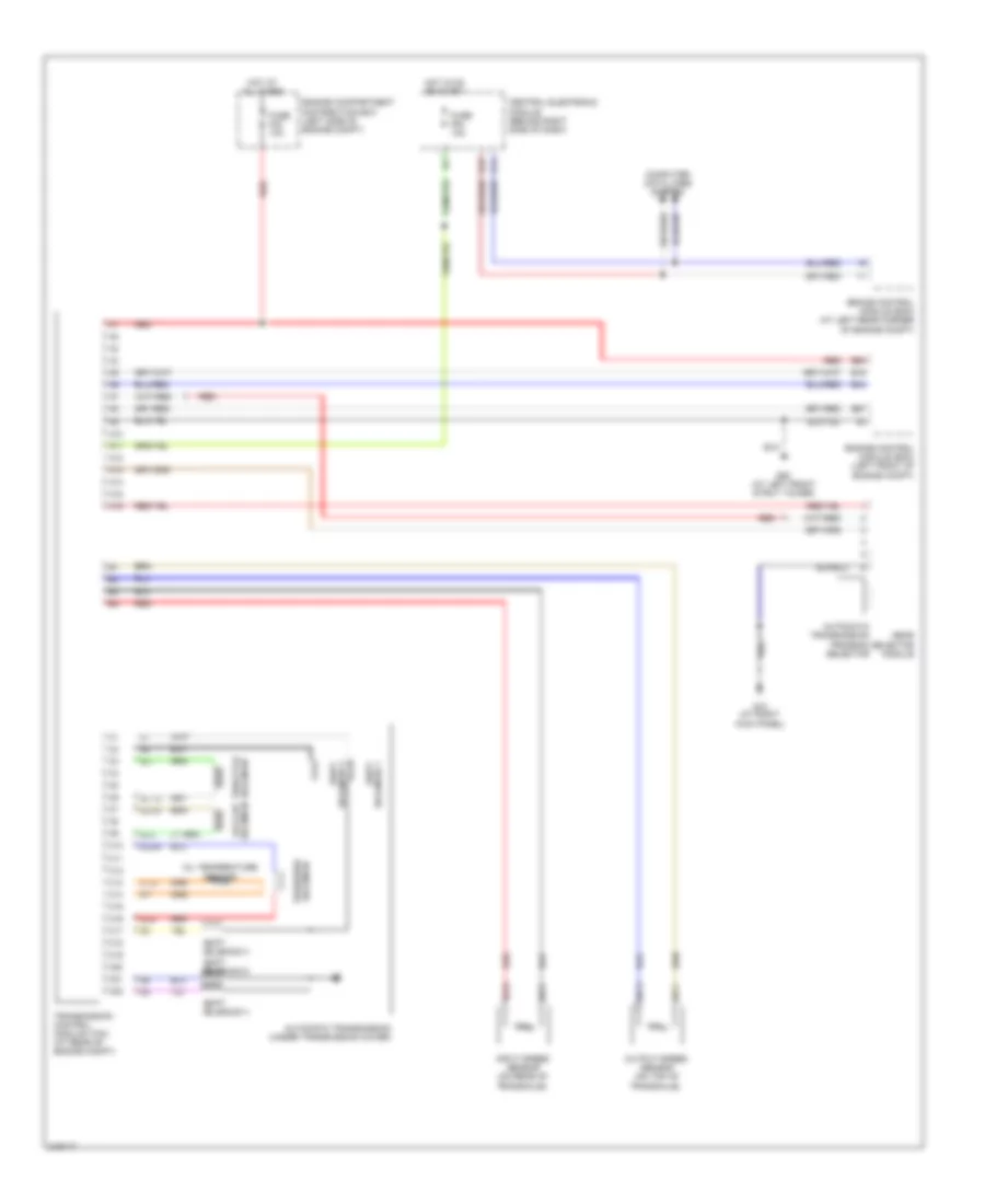
Transmission Wiring Diagram for Volvo S40 2005
List of elements for Transmission Wiring Diagram for Volvo S40 2005:
- A10
- A11
- A12
- A13
- A14
- A15
- A16
- Automatic transmission (under transmission cover)
- Automatic transmission program selector
- B15
- B44
- B54
- B57
- Brake control module (bcm) (at left rear corner of engine compt)
- C10
- C11
- C12
- C13
- C14
- C15
- C16
- C17
- C18
- C19
- C20
- C21
- C22
- Central electronic module (behind right side of dash)
- Computer data lines system
- Engine compartment distribution box (left side of engine compt)
- Engine control module (ecm) (left front of engine compt)
- Fuse f23 10a
- Fuse f54 10a
- G10 (at right kick panel)
- G14
- G15
- G52 (at left front strut tower)
- Gear selector module
- Hot at all times
- Hot in on or start
- Input speed sensor (on rear of transaxle)
- Oil temperature sensor
- Otg
- Output speed sensor (on top of transaxle)
- Red
- Shift solenoid 1
- Shift solenoid 3
- Shift solenoid 4
- Shift solenoid 5
- Sls
- Slsg
- Slt
- Sltg
- Slu
- Slug
- Solenoid 2 shift
- Solenoid lock-up
- Solenoid pressure
- Solenoid throttle
- Sp1+
- Sp1-
- Sp2+
- Sp2-
- Transmission control module (tcm) (at rear of engine compt)
 English