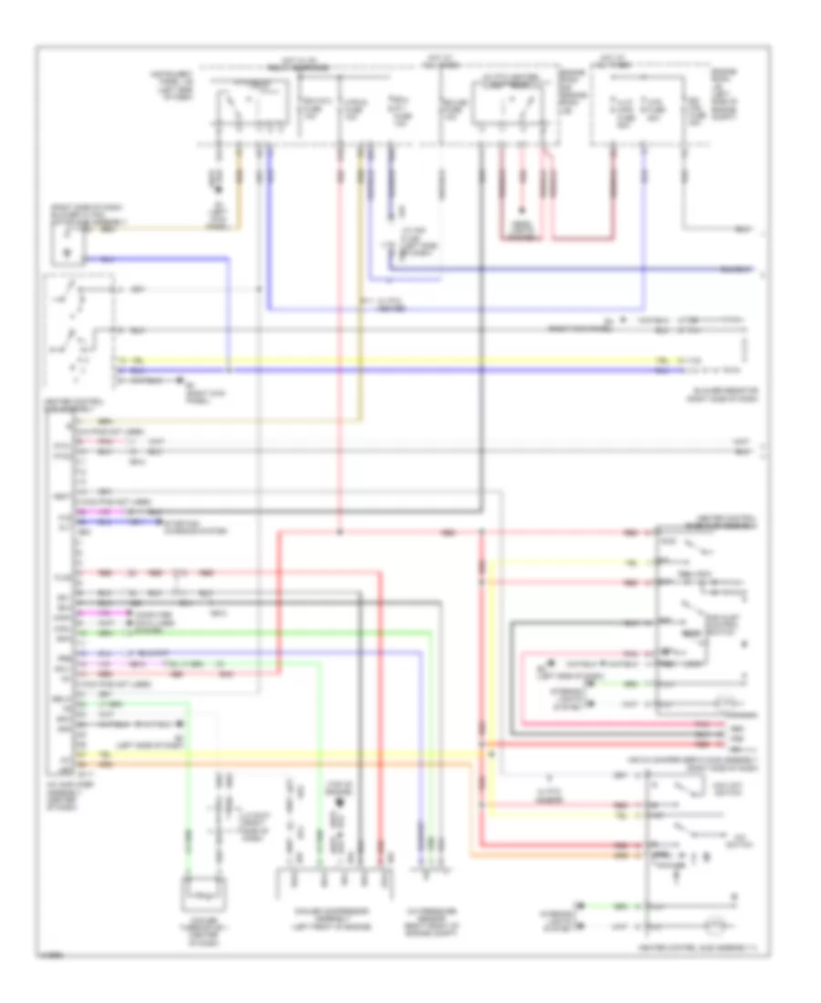
AIR CONDITIONING
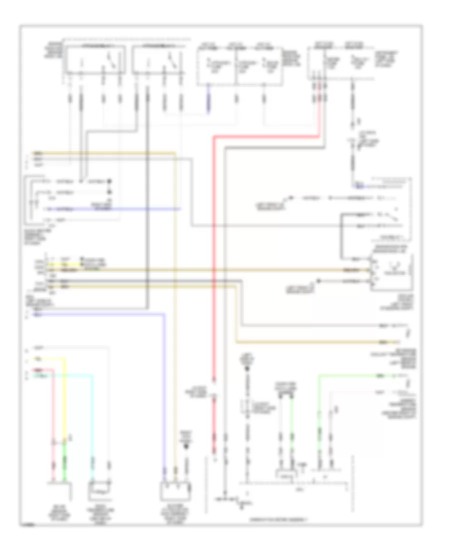
Automatic A/C Wiring Diagram, NUMMI Made (1 of 2) for Toyota Corolla 2011

List of elements for Automatic A/C Wiring Diagram, NUMMI Made (1 of 2) for Toyota Corolla 2011:
- (left side of dash) e2
- A/c amplifier assembly (center of dash)
- A/c blower assembly (center of dash)
- A/c evaporator temperature sensor
- A/c pressure sensor (right front of engine compt)
- Ae11
- Ae12
- Ae3
- Ae6
- Alt
- B bus
- B25
- B3 (top of engine)
- B94
- B97
- Ba1
- Ba2
- Blw
- Bus
- Bus g
- Canh
- Canl
- Computer data lines system
- Connector housing color (black)
- Connector housing color (red)
- Cooler compressor assembly (left front of engine)
- Damper servo motor (air inlet)
- Damper servo motor (air mix)
- Damper servo motor (air vent mode)
- Daytime running light relay (right side of dash)
- Defogger system
- E2 (left side of dash)
- E30
- Ecu-b2 fuse 10a
- Ecu-ig 2 fuse 10a
- Engine room j/b (left side of engine compt)
- Engine room r/b (engine room j/b)
- Floq
- Gnd
- H-lp
- H-lp relay
- Heater control sub-assembly
- Hls
- Hot at all times
- Hot in on or start
- Htr fuse 50a
- Htr-ig fuse 10a
- Ig+
- Ill+
- Ill-
- Instrument panel j/b (left side of dash)
- Interior lights system
- Lin1
- Pnk
- Pre
- Ptc1
- Ptc2
- Q10
- Qufl
- Rdfg
- Rdi fuse 40a
- Rear window defogger switch
- Red
- S5-1
- S5-3
- S5-4
- S5fl
- Sg-1
- Sg-2
- Sg-4
- Sga
- Sgfl
- Short pin
- Sol+
- Sol-
- Starting/ charging system
- Tea
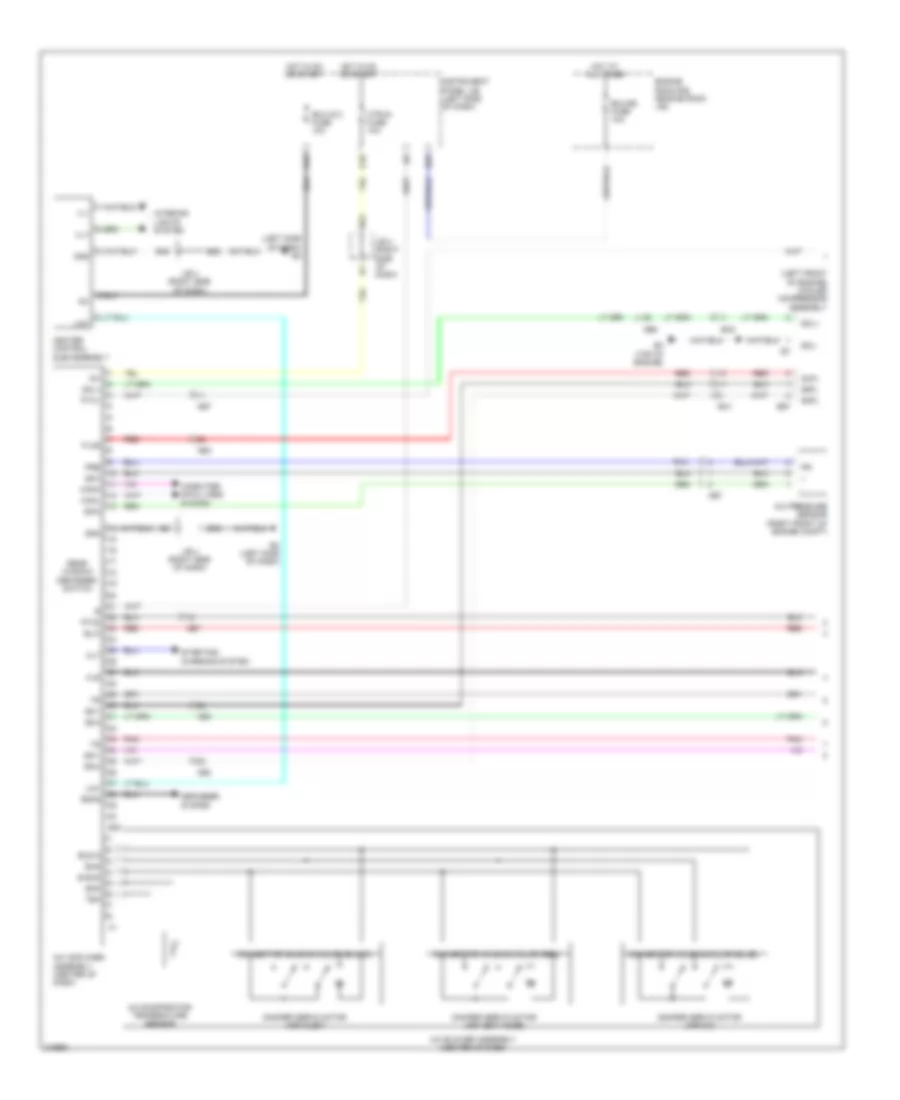
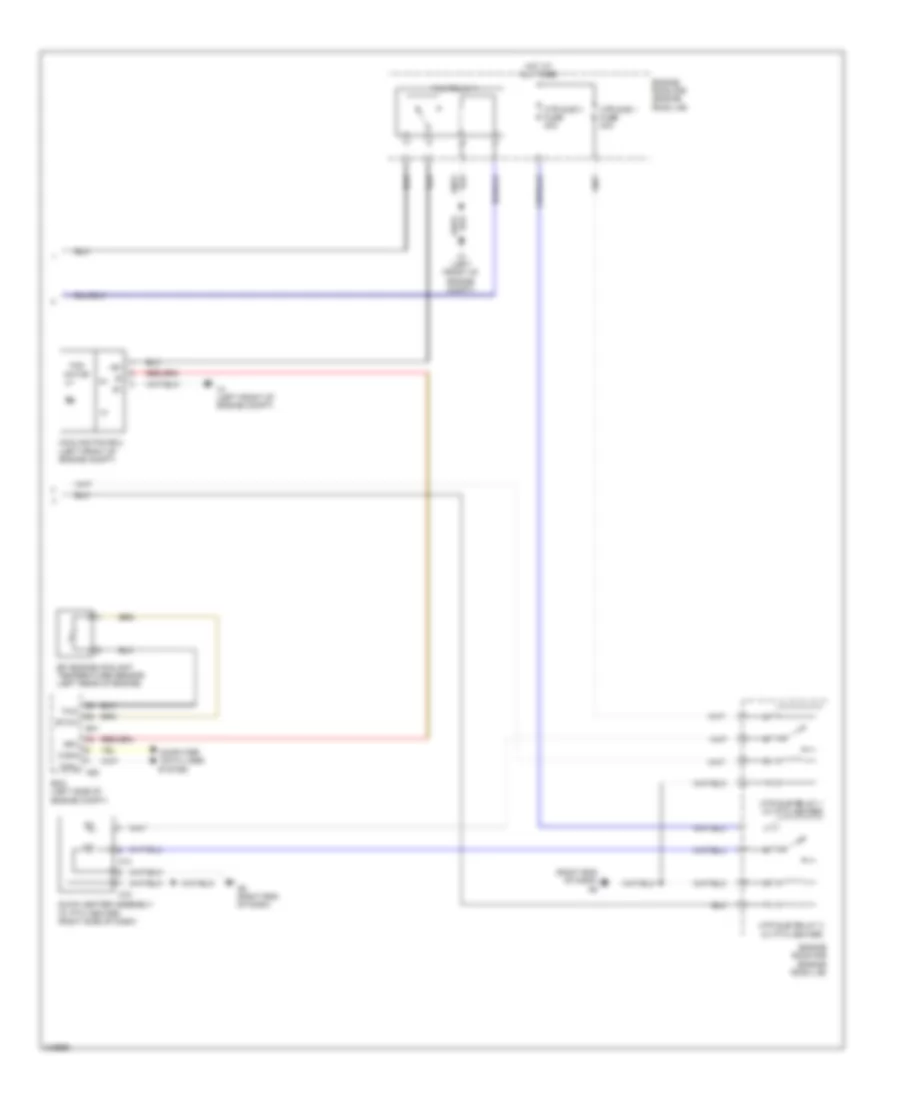
Automatic A/C Wiring Diagram, NUMMI Made (2 of 2) for Toyota Corolla 2011
List of elements for Automatic A/C Wiring Diagram, NUMMI Made (2 of 2) for Toyota Corolla 2011:
- (engine room j/b)
- (left front of
- (left side of dash) e2
- (right kick panel) e4
- +b1
- 5v ic
- 5v+b
- A1 (left front of engine compt)
- A14
- A15
- A45
- A50
- A6 (right end of dash)
- Ae3
- Ambient temperature sensor (center front of engine compt)
- B24
- B30
- B31
- Blower w/ fan motor sub assembly (right side of dash)
- Can i/f
- Canh
- Canl
- Combination meter assembly
- Computer data lines system
- Cooling fan ecu (left front of engine compt)
- Cpu
- Ecm (left side of engine compt)
- Ecu ig 1 fuse 10a
- Ecu-b fuse 10a
- Ef1
- Efi engine coolant temperature sensor (left rear of engine)
- Engine compt)
- Engine room r/b
- Engine room r/b (engine room j/b)
- Ethw
- Fan motor
- Fan relay 1
- Gnd
- H12
- Hot at all times
- Hot in on or start
- Htr sub 1 fuse 30a
- Htr sub 3 fuse 30a
- Htr sub relay 1
- Htr sub relay 3
- I/f
- Ig+
- Instrument panel j/b (left side of dash)
- J/c a45 & a46 (left side of dash) a46
- J/c e107 (right side of dash)
- Meter fuse 7.5a
- Pnk
- Quick heater assembly (right side of dash)
- Red
- Rfc
- Room temperature sensor (center of dash)
- Solar sensor (right side of dash)
- Temp
- Thw
- Tx1+
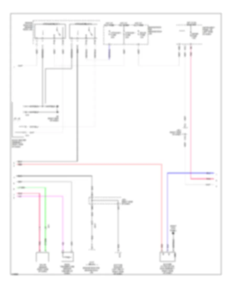
Automatic A/C Wiring Diagram, TMC Made (1 of 3) for Toyota Corolla 2011
List of elements for Automatic A/C Wiring Diagram, TMC Made (1 of 3) for Toyota Corolla 2011:
- (left front of engine) cooler compressor assembly
- (left side of dash) e2
- A/c amplifier assembly (center of dash)
- A/c blower assembly (center of dash)
- A/c evaporator temperature sensor
- A/c pressure sensor (right front of engine compt)
- Ae3
- Ae6
- Ae7
- Alt
- B bus
- B25
- B3 (top of engine)
- B46
- B51
- B58
- B97
- Ba1
- Ba2
- Blw
- Bus
- Bus g
- Canh
- Canl
- Computer data lines system
- Connector housing color (black)
- Connector housing color (red)
- Damper servo motor (air inlet)
- Damper servo motor (air mix)
- Damper servo motor (air vent mode)
- Defogger system
- E2 (left side of dash)
- E30
- Ecu-b2 fuse 10a
- Ecu-ig 2 fuse 10a
- Engine room r/b (engine room j/b)
- Floq
- Gnd
- Heater control sub-assembly
- Hls
- Hot at all times
- Hot in on or start
- Htr-ig fuse 10a
- Ig+
- Ill+
- Ill-
- Instrument panel j/b (left side of dash)
- Interior
- J/b 4 (right side of dash)
- Lights system
- Lin1
- Pnk
- Pre
- Ptc1
- Ptc2
- Q10
- Qufl
- Rdfg
- Rear window defogger switch
- Red
- S15
- S5-1
- S5-3
- S5-4
- S5fl
- Sg-1
- Sg-2
- Sg-4
- Sga
- Sgfl
- Sol+
- Sol-
- Starting/ charging system
- Tea
Automatic A/C Wiring Diagram, TMC Made (2 of 3) for Toyota Corolla 2011
List of elements for Automatic A/C Wiring Diagram, TMC Made (2 of 3) for Toyota Corolla 2011:
- (right kick panel) e4
- A14
- A15
- A21
- A6 (right end of dash)
- Ae11
- B30
- B69
- B71
- Blower w/ fan motor sub assembly (right side of dash)
- C15
- Daytime running light relay (right side of dash)
- Ecu-b fuse 10a
- Ef1
- Engine room r/b (engine room j/b)
- Gnd
- H-lp
- H-lp relay
- H12
- Hot at all times
- Hot in on or start
- Htr sub 1 fuse 30a
- Htr sub 3 fuse 30a
- Htr sub relay 1
- Htr sub relay 3
- Instrument panel j/b (left side of dash)
- J/b 4 (right side of dash)
- Meter fuse 7.5a
- Pnk
- Quick heater assembly (right side of dash)
- Red
- Room temperature sensor (center of dash)
- Solar sensor (right side of dash)
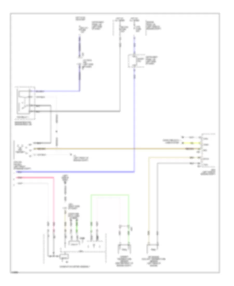
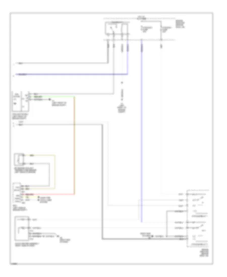
Automatic A/C Wiring Diagram, TMC Made (3 of 3) for Toyota Corolla 2011
List of elements for Automatic A/C Wiring Diagram, TMC Made (3 of 3) for Toyota Corolla 2011:
- (left side of dash) e2
- +b1
- 5v ic
- 5v+b
- A1 (left front of engine compt)
- A45
- A50
- Ae3
- Ambient temperature sensor (center front of engine compt)
- B21
- B24
- B31
- B58
- Can i/f
- Canh
- Canl
- Combination meter assembly
- Computer data lines system
- Cooling fan ecu (left front of engine compt)
- Cpu
- Ecm (left side of engine compt)
- Ecu ig 1 fuse 10a
- Efi engine coolant temperature sensor (left rear of engine)
- Engine room j/b (left side of engine compt)
- Engine room r/b (engine room j/b)
- Ethw
- Fan motor
- Fan relay 1
- Hot at all times
- Hot in on or start
- Htr fuse 50a
- I/f
- Ig+
- Instrument panel j/b (left side of dash)
- J/b 4 (right side of dash)
- J/c a45 & a46 (left side of dash) a46
- Pnk
- Rdi fan fuse 40a
- Rfc
- Short pin
- Temp
- Thw
- Tx1+
Manual A/C Wiring Diagram, NUMMI Made (1 of 2) for Toyota Corolla 2011
List of elements for Manual A/C Wiring Diagram, NUMMI Made (1 of 2) for Toyota Corolla 2011:
- (15-20 pins not used)
- (15-22 pins not used)
- (2-8 pins not used)
- (right side of dash) blower w/ fan motor sub assembly
- (top of engine) b3
- (w/ ptc heater) h-lp relay
- A/c
- A/c amplifier assembly (center of dash)
- A/c pressure sensor (right front of engine compt)
- A/c switch
- A/c+
- A45
- Acid
- Ae11
- Ae12
- Ae3
- Ae6
- Aind
- Air inlet control switch
- Air mix damper servo sub assembly (right side of dash)
- Alt
- B24
- B25
- B94
- B97
- Ba1
- Ba2
- Blower resistor (right side of dash)
- Canh
- Canl
- Computer data lines system
- Cooler compressor assembly (left front of engine)
- Cooler thermistor 1 (center of dash)
- Def-logic
- E1 (left kick panel)
- E111
- E17
- E2 (left side of dash)
- E4 (right kick panel)
- E63
- Ecu-
- Ecu-b2 fuse 10a
- Ecu-ig 2 fuse 10a
- Engine room j/b (left side of engine compt)
- Engine room r/b (engine room j/b)
- F/d
- Floq
- Free
- Frs
- Gnd
- H-lp main fuse 50a
- Head- lights system
- Heat
- Heater control base sub-assembly
- Heater control sub assembly
- Heater control sub assembly 3
- Hls
- Hot at all times
- Hot w/ ig1 relay energized
- Htr fuse 50a
- Htr relay
- Htr-ig fuse 10a
- Ig 1 fuse 10a
- Ig+
- Ill+
- Ill-
- Instrument panel j/b (left side of dash)
- Interior lights system
- J/c a45 & a46 (left side of dash) a46
- J/c e107 (right side of dash)
- Led
- Led+
- Lock
- Max hot switch
- Pnk
- Pre
- Ptc1
- Ptc2
- Q10
- Qufl
- Rdi fan fuse 40a
- Rec
- Red
- S5-1
- S5-3
- S5fl
- Sblw
- Sg-2
- Sg-3
- Sgfl
- Sol+
- Sol-
- Starting/ charging system
- W/ ptc heater
Manual A/C Wiring Diagram, NUMMI Made (2 of 2) for Toyota Corolla 2011
List of elements for Manual A/C Wiring Diagram, NUMMI Made (2 of 2) for Toyota Corolla 2011:
- (right end of dash) a6
- +b1
- A1 (left front of engine compt)
- A14
- A15
- A50
- A6 (right end of dash)
- B31
- Canh
- Canl
- Computer
- Cooling fan ecu (left front of engine compt)
- Data lines
- Ecm (left side of engine compt)
- Efi engine coolant temperature sensor (left rear of engine)
- Engine room r/b (engine room j/b)
- Ethw
- Fan motor
- Fan relay 1
- Hot at all times
- Htr sub 1 fuse 30a
- Htr sub 3 fuse 30a
- Htr sub relay 1 (w/ ptc heater)
- Htr sub relay 3 (w/ ptc heater)
- Quick heater assembly (w/ ptc heater) (right side of dash)
- Rfc
- System
- Thw
Manual A/C Wiring Diagram, TMC Made (1 of 2) for Toyota Corolla 2011
List of elements for Manual A/C Wiring Diagram, TMC Made (1 of 2) for Toyota Corolla 2011:
- (15-20 pins not used)
- (15-22 pins not used)
- (2-8 pins not used)
- (right kick panel) e4
- (right side of dash) blower w/ fan motor sub assembly
- (right side of dash) j/b 4
- (top of engine) b3
- A/c
- A/c amplifier assembly (center of dash)
- A/c pressure sensor (right front of engine compt)
- A/c switch
- A/c+
- A45
- A55
- A60
- A75
- Acid
- Ae11
- Ae3
- Ae6
- Ae7
- Aind
- Air inlet control switch
- Air mix damper servo sub assembly (right side of dash)
- Alt
- B12
- B24
- B25
- B37
- B38
- B44
- B45
- B48
- B51
- B57
- B58
- B69
- B97
- Ba1
- Ba2
- Blower resistor (right side of dash)
- Canh
- Canl
- Computer data lines system
- Cooler compressor assembly (left front of engine)
- Cooler thermistor 1 (center of dash)
- Def-logic
- E1 (left kick panel)
- E111
- E17
- E2 (left side of dash)
- E4 (right kick panel)
- E63
- Ecu-
- Ecu-b2 fuse 10a
- Ecu-ig 2 fuse 10a
- Engine room j/b (left side of engine compt)
- Engine room r/b (engine room j/b)
- F/d
- Floq
- Free
- Frs
- Gnd
- H-lp main fuse 50a
- H-lp relay
- Head- lights system
- Heat
- Heater control base sub-assembly
- Heater control sub assembly
- Heater control sub assembly 3
- Hls
- Hot at all times
- Hot w/ ig1 relay energized
- Htr fuse 50a
- Htr relay
- Htr-ig fuse 10a
- Ig 1 fuse 10a
- Ig+
- Ill+
- Ill-
- Instrument panel j/b (left side of dash)
- Interior lights system
- J/b 4 (right side of dash)
- J/c a45 & a46 (left side of dash) a46
- J/c e107 (right side of dash)
- Led
- Led+
- Lock
- Max hot switch
- Pnk
- Pre
- Ptc1
- Ptc2
- Q10
- Qufl
- Rdi fan fuse 40a
- Rec
- Red
- S5-1
- S5-3
- S5fl
- Sblw
- Sg-2
- Sg-3
- Sgfl
- Sol+
- Sol-
- Starting/ charging system
Manual A/C Wiring Diagram, TMC Made (2 of 2) for Toyota Corolla 2011
List of elements for Manual A/C Wiring Diagram, TMC Made (2 of 2) for Toyota Corolla 2011:
- (right end of dash) a6
- +b1
- A1 (left front of engine compt)
- A14
- A15
- A50
- A6 (right end of dash)
- B31
- Canh
- Canl
- Computer
- Cooling fan ecu (left front of engine compt)
- Data lines
- Ecm (left side of engine compt)
- Efi engine coolant temperature sensor (left rear of engine)
- Engine room r/b (engine room j/b)
- Ethw
- Fan motor
- Fan relay 1
- Hot at all times
- Htr sub 1 fuse 30a
- Htr sub 3 fuse 30a
- Htr sub relay 1
- Htr sub relay 3
- Quick heater assembly (right side of dash)
- Rfc
- System
- Thw