AIR CONDITIONING
A/C Wiring Diagram for Toyota Corolla LE 1994

List of elements for A/C Wiring Diagram for Toyota Corolla LE 1994:
- (1.8l a/t) (1.8l m/t & 1.6l)
- (left front of engine compt)
- A/c amplifier (right side of i/p)
- A/c condenser fan motor (right front of engine compt)
- A/c condenser fan relay n0. 3
- A/c condenser fan relay no. 2
- A/c dual pressure switch (right rear of engine compt)
- A/c fuse
- A/c high pressure switch (left front of engine compt)
- A/c magnet clutch (right front of engine)
- A/c switch
- A/c thermistor (right side of i/p)
- A10 b10
- A17
- A21 b6
- Blower motor (right side of i/p)
- Blower resistor (right side of i/p)
- C14
- Cds fuse 30a
- D11
- Ecu-ig fuse 15a
- Engine control module (right side of i/p)
- Fan fusible link 30a
- G100 (front left fender)
- G203 (right kick panel)
- Gauge fuse 10a
- Heater blower switch
- Heater fuse 40a
- Heater relay
- Hot at all times
- Hot in on or start
- Hot in run or start
- Integration relay
- Interior lights system
- J/b 1 (left kick panel)
- J/b 1 (left side of i/p)
- J/b 2
- J/b 2 (left side of engine compt)
- J/b 3 (center of i/p)
- J/b 4 (right kick panel)
- Magnet clutch relay
- Off
- R/b 5 (left side of engine compt)
- Radiator fan motor
- Radiator fan relay no. 1
- Red
- Water temperature switch (right radiator support)
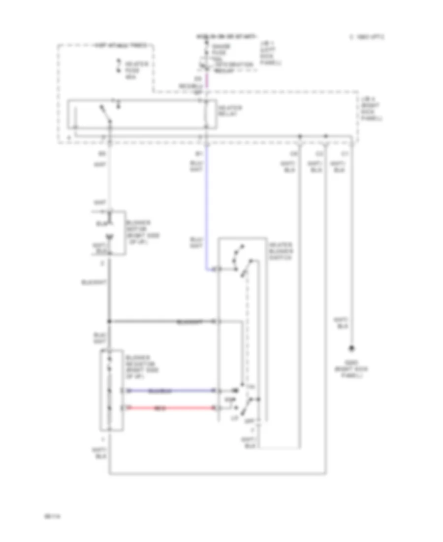
Heater Wiring Diagram for Toyota Corolla LE 1994
List of elements for Heater Wiring Diagram for Toyota Corolla LE 1994:
- (right side
- Blower motor
- Blower resistor (right side of i/p)
- C 1995 vftc
- G203 (right kick panel)
- Gauge fuse 10a integration relay
- Heater blower switch
- Heater fuse 40a
- Heater relay
- Hot at all times
- Hot in on or start
- J/b 1 (left kick panel)
- J/b 4 (right kick panel)
- Of i/p)
- Off
- Red