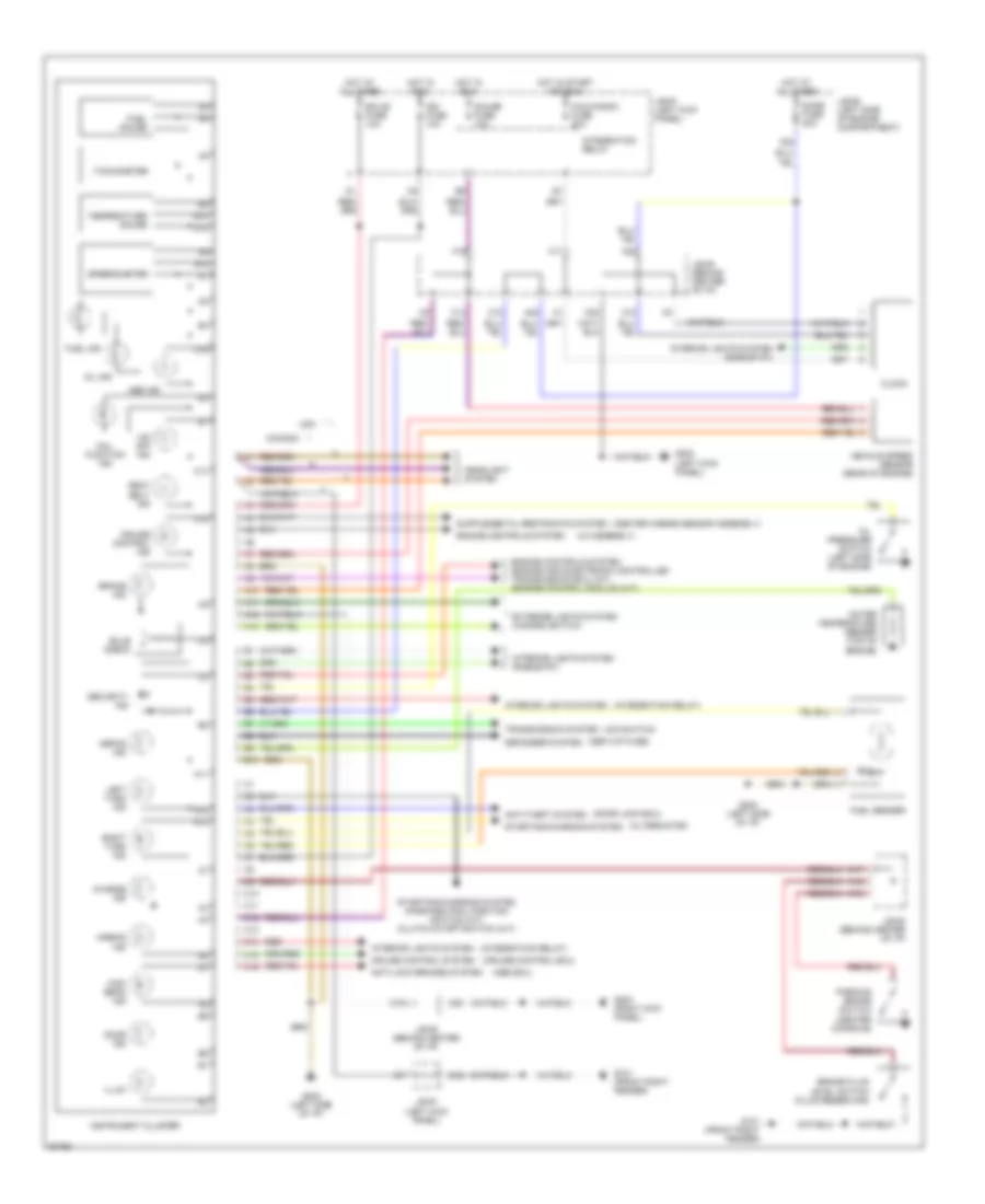
INSTRUMENT CLUSTER
Instrument Cluster Wiring Diagram for Toyota Corolla LE 1994
List of elements for Instrument Cluster Wiring Diagram for Toyota Corolla LE 1994:
- (abs ecu)
- (alternator)
- (center airbag sensor assembly)
- (cruise control ecu)
- (def-i/up fuse)
- (door lock ecu)
- (iia assembly)
- (integration relay)
- (o/d switch)
- 0/d off ind
- A10
- A11
- A12
- A13
- A16
- A19
- A22
- Abs ind
- Airbag ind
- Anti-lock brakes system
- Anti-theft system
- B10
- Brake fluid level switch (fluid reservoir)
- Brake ind
- Bulb check
- C10
- C11
- C12
- C13
- C14
- C15
- C16
- C17
- C19
- C20
- Canada
- Charge ind
- Cig & radio fuse 20a
- Clock
- Cruise control ind
- Cruise control system
- Defog ind
- Defogger system
- Dome fuse 20a
- Door ind
- Ecu-b fuse 10a
- Engine controls system
- Engine controls system (engine and electronic controlled transmission ecu) (a/t) (engine control module) (m/t)
- Exterior lights system (hazard switch)
- Fuel gauge
- Fuel ind
- Fuel sender
- G101 (front right fender)
- G200 (left kick panel)
- G202 (left side of i/p)
- G203 (right kick panel)
- Gauge fuse 10a
- Headlight system
- High beam ind
- Hot at all times
- Hot in run
- Hot in start and run
- Ign fuse 10a
- Illum
- Instrument cluster
- Integration relay
- Interior lights system
- Interior lights system (rheostat)
- J/b #1 (left kick panel)
- J/b #2 (left side of engine compartment)
- J/b #3 (behind center of i/p)
- Left turn ind
- Mal- function ind
- Oil ind
- Oil pressure switch (left side of engine)
- Parking brake switch (center console)
- Red
- Right turn ind
- Seat belt ind
- Security ind
- Speedometer
- Starting/charging system
- Starting/charging system (park/neutral position switch) (a/t) (clutch start switch) (m/t)
- Tachometer
- Temperature gauge
- Transmission system
- Usa
- Vehicle speed sensor (rear of engine)
- Water temperature sender (top of engine)
 English