AIR CONDITIONING
A/C Wiring Diagram for Toyota Tacoma SR5 1997

List of elements for A/C Wiring Diagram for Toyota Tacoma SR5 1997:
- (3.4l m/t canada)
- (cowl harness, at right kick panel)
- (cowl harness, behind top right side of i/p)
- (except 3.4l m/t canada)
- 1995 vftc c
- 2.4l, 2.7l m/t
- 2.7l a/t
- 3.4l a/t
- 3.4l m/t
- 40a
- A/c amplifier (right side of i/p)
- A/c dual pressure switch (center of i/p)
- A/c fuse 10a
- A/c magnetic clutch
- A/c switch
- A/c thermistor (right side of i/p)
- A20
- Alt fuse 80a
- Blower motor
- Blower resistor (right side of i/p)
- Defroster mode switch
- E10
- Engine control module (behind right side of i/p)
- F14
- F15
- F16
- F20
- G100 (front left fender)
- G200 (left kick panel)
- G203 (right kick panel)
- Gauge fuse 10a
- Heater blower switch
- Heater fuse
- Heater relay
- Hot at all times
- Hot in run or start
- I11
- I13
- I14 (a/c harness, below glove box)
- I5 (cowl harness, behind left top of i/p)
- J/b 1 (left kick panel)
- J/b 3 (behind center of i/p)
- J/b 3 (behind center of instrument panel)
- J/c 1 (right front of engine compt)
- Off
- R/b 2 (left side of engine compt)
- Red
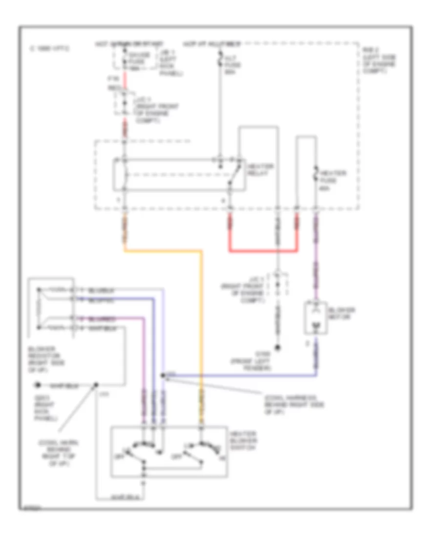
Heater Wiring Diagram for Toyota Tacoma SR5 1997
List of elements for Heater Wiring Diagram for Toyota Tacoma SR5 1997:
- (cowl harn, behind right top of i/p)
- (cowl harness, behind right side of i/p)
- 1995 vftc c
- 40a
- Alt fuse 80a
- Blower motor
- Blower resistor (right side of i/p)
- F16
- G100 (front left fender)
- G203 (right kick panel)
- Gauge fuse 10a
- Heater blower switch
- Heater fuse
- Heater relay
- Hot at all times
- Hot in run or start
- I11
- I13
- J/b 1 (left kick panel)
- J/c 1 (right front of engine compt)
- Off
- R/b 2 (left side of engine compt)
- Red