ENGINE PERFORMANCE
2.4L
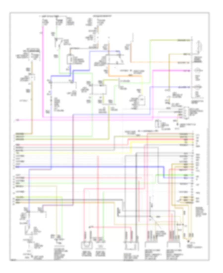
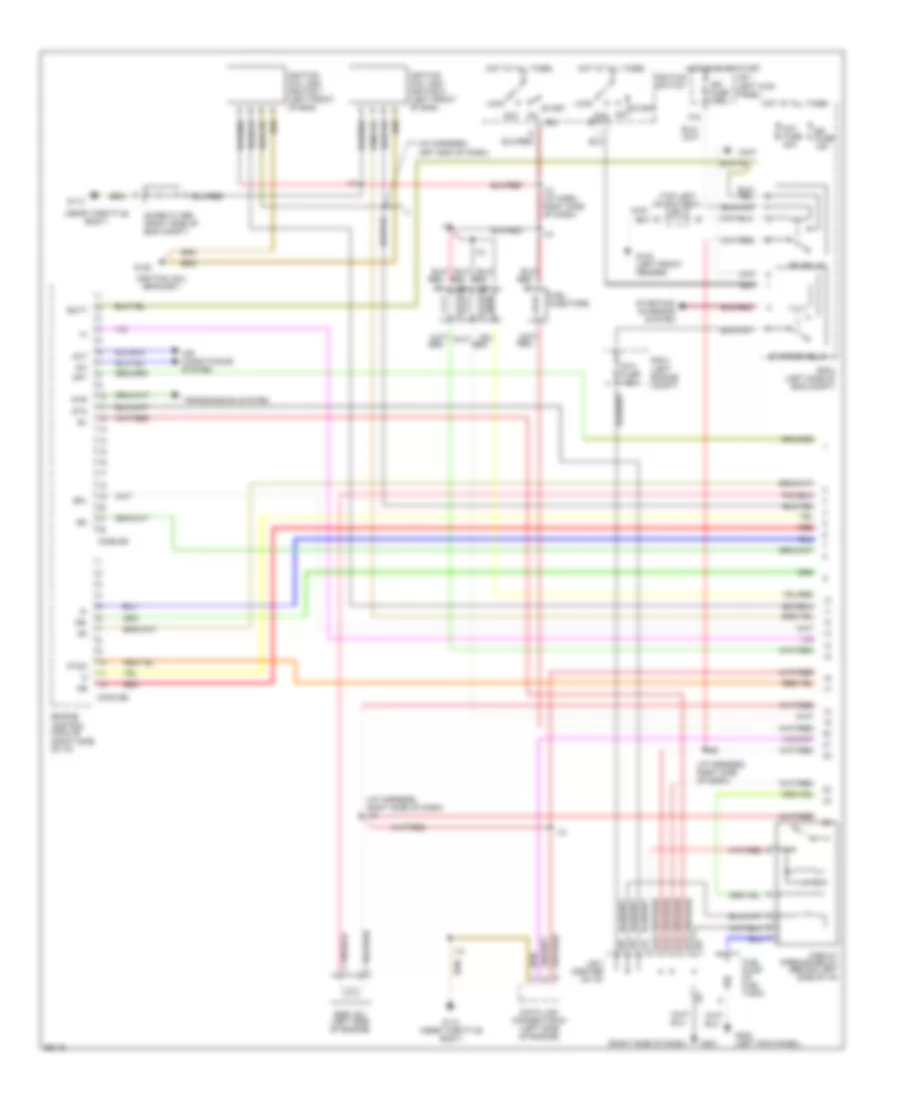
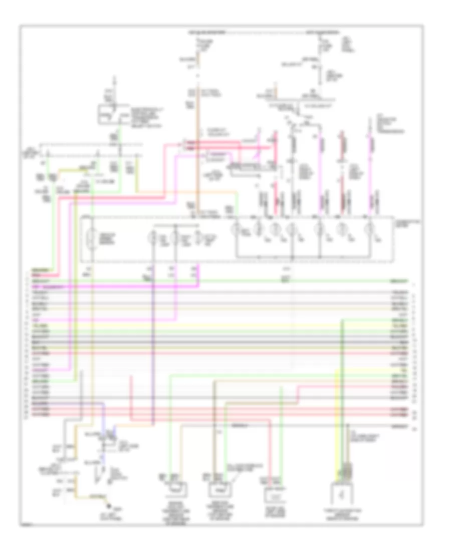
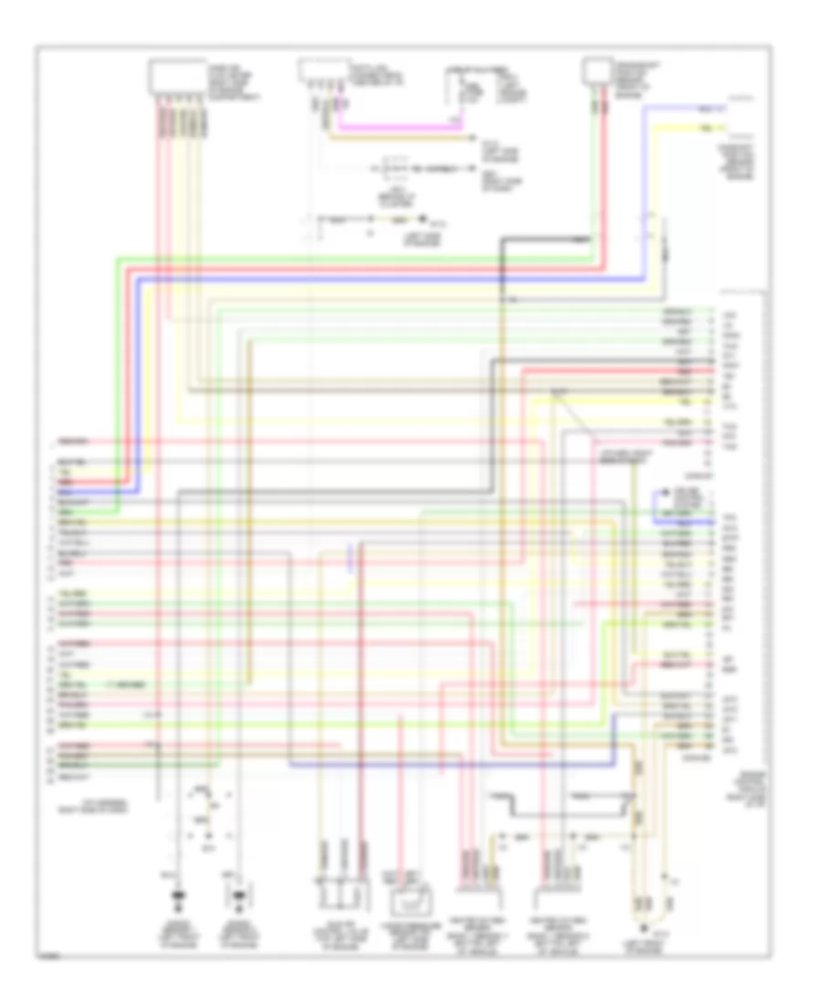
2.4L, Engine Performance Wiring Diagrams (1 of 2) for Toyota Tacoma SR5 1997

List of elements for 2.4L, Engine Performance Wiring Diagrams (1 of 2) for Toyota Tacoma SR5 1997:
- (eng harn, left of battery)
- (eng harn, rear of left frt fender)
- (eng harn, top left side of engine)
- (front left fender)
- (i/p harn, right side of dash)
- (left
- (left engine compt)
- (left kick panel)
- (left side of engine compartment)
- (left side of engine)
- (near throttle body)
- (right side of dash)
- (tachometer)
- (top left of battery) j/c 1
- A/t only
- Acc
- Acc st1
- Aci
- Act
- Air conditioning system (a/c amplifier)
- Am1 fuse 40a
- Batt
- Circuit opening relay (behind left side of i/p)
- Cluster system
- Conn e5
- Conn e7
- Crankshaft position sensor (center front of engine)
- Cruise control system
- Data link connector #1 (left side of engine)
- Distributor (right front side of engine)
- E12
- E13
- E14
- E15
- Efi fuse 15a
- Efi relay
- Egr gas temperature sensor (top left of engine)
- Els
- Engine control module (right side of i/p)
- Engine coolant temperature sensor (center rear of engine)
- F15
- Fuel injectors
- Fuel pump (in fuel tank)
- G102
- G113
- G113 (near throttle body)
- G201
- G202
- Hot at all times
- Hot in on or start
- I10
- Idl
- Ig2
- Ign fuse 7.5a
- Igniter
- Ignition switch
- Instrument
- J/b 1 (left kick panel)
- J/b 3 (center of i/p)
- Knk
- Knock sensor (right side of engine)
- Lock
- Mass air flow meter (right side engine compt)
- Nca
- Noise filter
- Nsw
- Ox1
- Ox2
- Pnk
- R/b 2
- R/b 2 engine compt)
- Red
- Sdl
- Sp1
- Sta
- Sta fuse 7.5a
- Start
- Starter relay
- Starting
- System
- Te1
- Tha
- Thg
- Throttle position sensor
- Thw
- Vcc
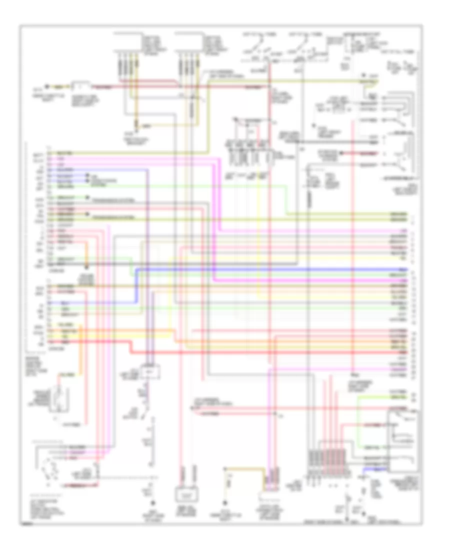
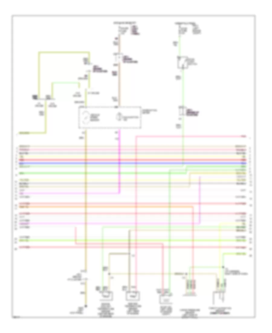
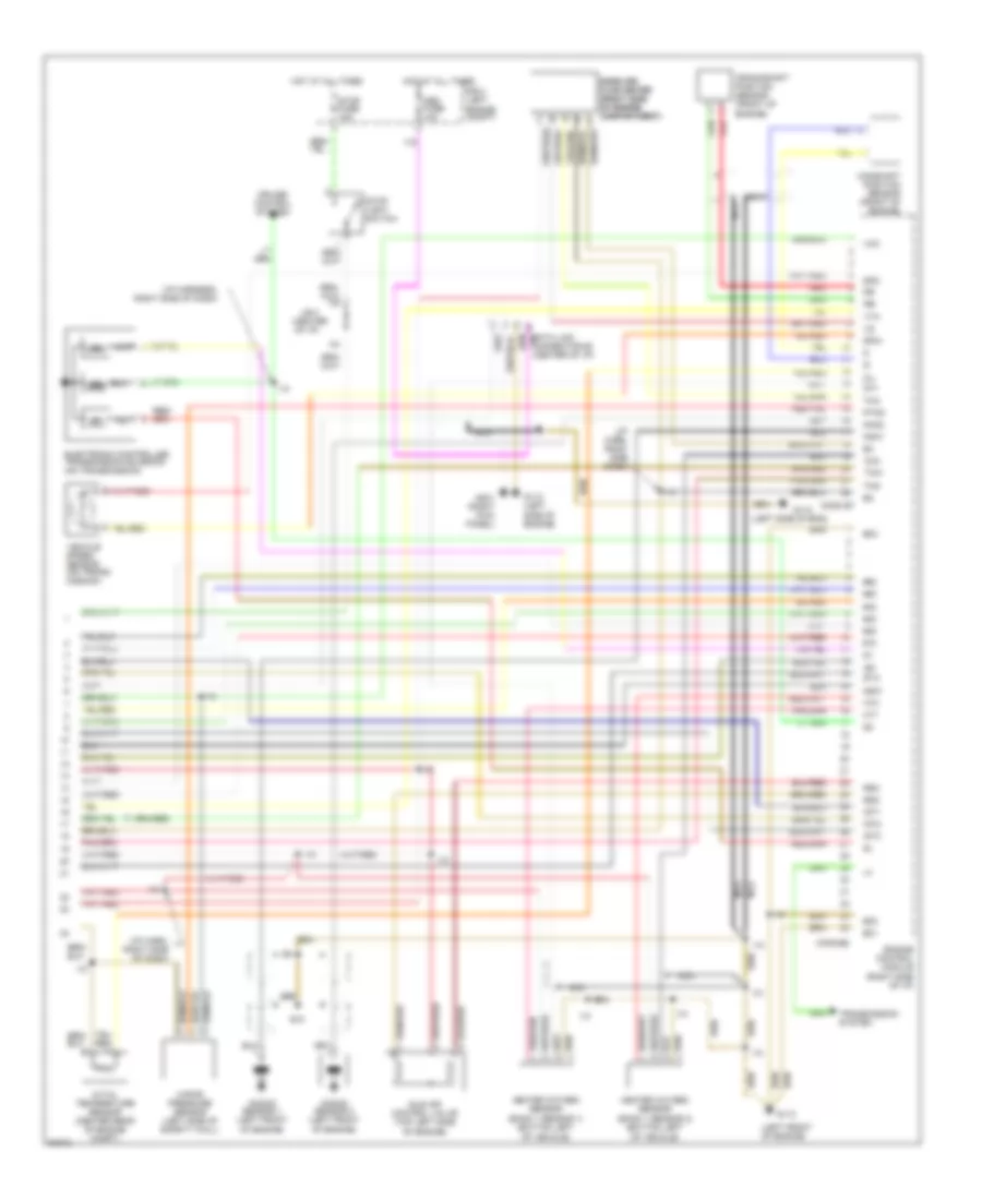
2.4L, Engine Performance Wiring Diagrams (2 of 2) for Toyota Tacoma SR5 1997
List of elements for 2.4L, Engine Performance Wiring Diagrams (2 of 2) for Toyota Tacoma SR5 1997:
- #10
- #20
- (a/t only)
- (at left kick panel)
- (center of i/p)
- (i/p harn, right side of dash)
- (left side of dash)
- (near throttle body)
- (right side of dash)
- A/t only
- C12
- C13
- Combination meter
- Conn e8
- Cruise control ecu (right kick panel)
- D j/c 4 (left side of i/p)
- D10
- D12
- D16
- D17
- D18
- D19
- Data link connector #3 (center of i/p)
- E01
- E02
- E03
- Egr
- Egr vsv (left side of engine)
- Engine control module (right side of i/p)
- Evap vsv (left side of engine)
- G113
- G201
- G202
- Gauge fuse 10a
- Heated oxygen sensor (bank 1 sensor 1) (bottom left of vehicle)
- Heated oxygen sensor (bank 1 sensor 2) (bottom left of vehicle)
- Hot at all times
- Hot in on or start
- Hot with tail relay energized
- Ht1
- Ht2
- I10
- Idle air control valve (top left side of engine)
- Igf
- Igt
- Intake air temperature sensor (right side of engine compt)
- J/b 1 (left kick panel)
- J/b 3
- J/b 3 (behind i/p cluster)
- J/b 3 (center of dash)
- J/b 3 (center of i/p)
- J/c 4 (left side of i/p)
- Malf. ind. lamp
- Nca
- Ne-
- O/d
- O/d cut relay (right side eng compt)
- O/d diode (right side of i/p) (a/t w/ cruise)
- O/d ind. lamp
- O/d main switch (a/t)
- O/d solenoid (on trans- mission)
- Obd fuse 10a
- Panel fuse 10a
- Prg
- R/b 2 (left engine compt)
- R/b 2 (left side of eng compt)
- Red
- Rsc
- Rso
- Stop light switch
- Stop stop stop stop stop fuse 15a
- Vehicle speed sensor
- W/ cruise
- W/o cruise
2.7L
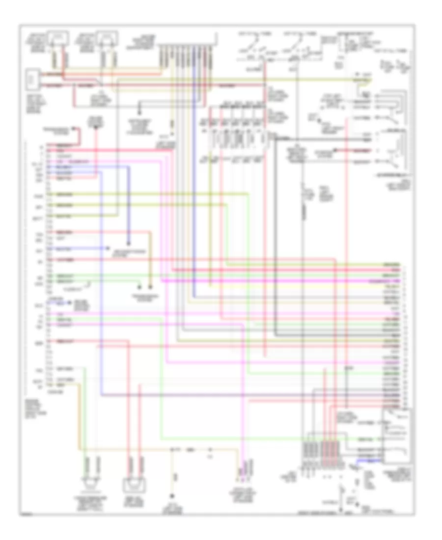
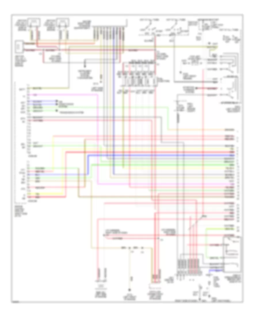
2.7L, Engine Performance Wiring Diagrams, A/T (1 of 3) for Toyota Tacoma SR5 1997
List of elements for 2.7L, Engine Performance Wiring Diagrams, A/T (1 of 3) for Toyota Tacoma SR5 1997:
- (eng harn, left front fender)
- (i/p harness, left end of dash)
- (i/p harness, right side of dash)
- (i/p harness, right side of dash) i10
- (ignition coil bracket)
- (left engine compt)
- (near throttle body)
- (right side of dash)
- (top left of battery) j/c 1
- 4wd
- A/t indicator switch (park neutral position switch) (on trans)
- Acc
- Acc st1
- Aci
- Act
- Air conditioning system
- Am1 fuse 40a
- Batt
- Circuit opening relay (behind left side of i/p)
- Conn e5
- Conn e6
- Cruise control system
- Data link connector #1 (left side of engine)
- E12
- E13
- E14
- E15
- Efi fuse 15a
- Efi relay
- Egr vsv (left side of engine)
- Els
- Engine control module (right side of i/p)
- F15
- Fuel injectors
- Fuel pump (in fuel tank)
- G102 (left front fender)
- G113
- G113 (near throttle body)
- G125
- G201
- G201 (right side of dash)
- G202 (left kick panel)
- Hot at all times
- Hot in on or start
- I10
- I10 (i/p harn, right side of dash)
- Ig2
- Ign fuse 7.5a
- Ignition coil and ignitor 1 (left front of eng)
- Ignition coil and ignitor 2 (left front of eng)
- Ignition switch
- J/b 1 (left kick panel)
- J/b 3 (center of i/p)
- J/c 4 (left side of dash)
- Lock
- Ne-
- Noise filter (right side of eng compt)
- Nsw
- O/d main switch
- Od1
- Od2
- Oil-w
- Pnk
- Ptnk
- Pwr
- R/b 2
- R/b 2 (left side of eng compt)
- Red
- Sdl
- Sp1
- Sp2+
- Sp2-
- Sta
- Sta fuse 7.5a
- Start
- Starter relay
- Starting/ charging system
- Tfn
- Transmission system
- Vehicle speed sensor (on trans)
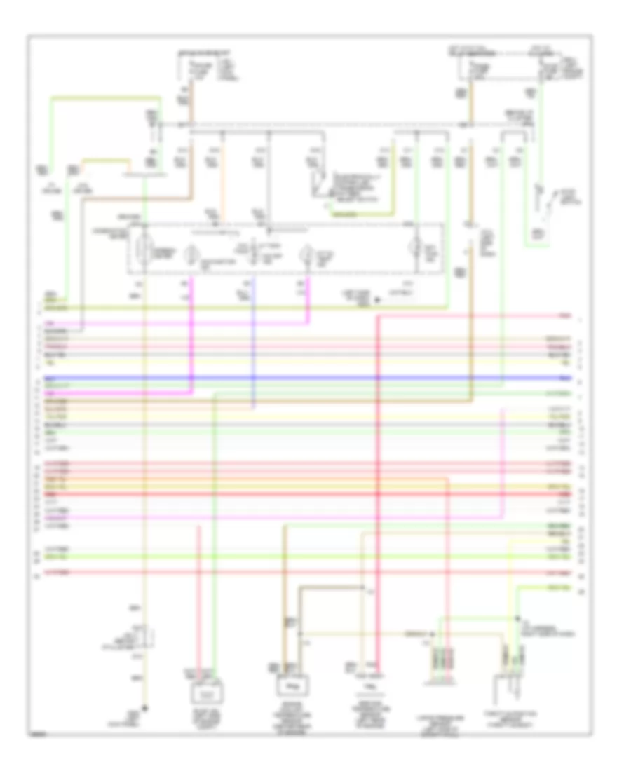
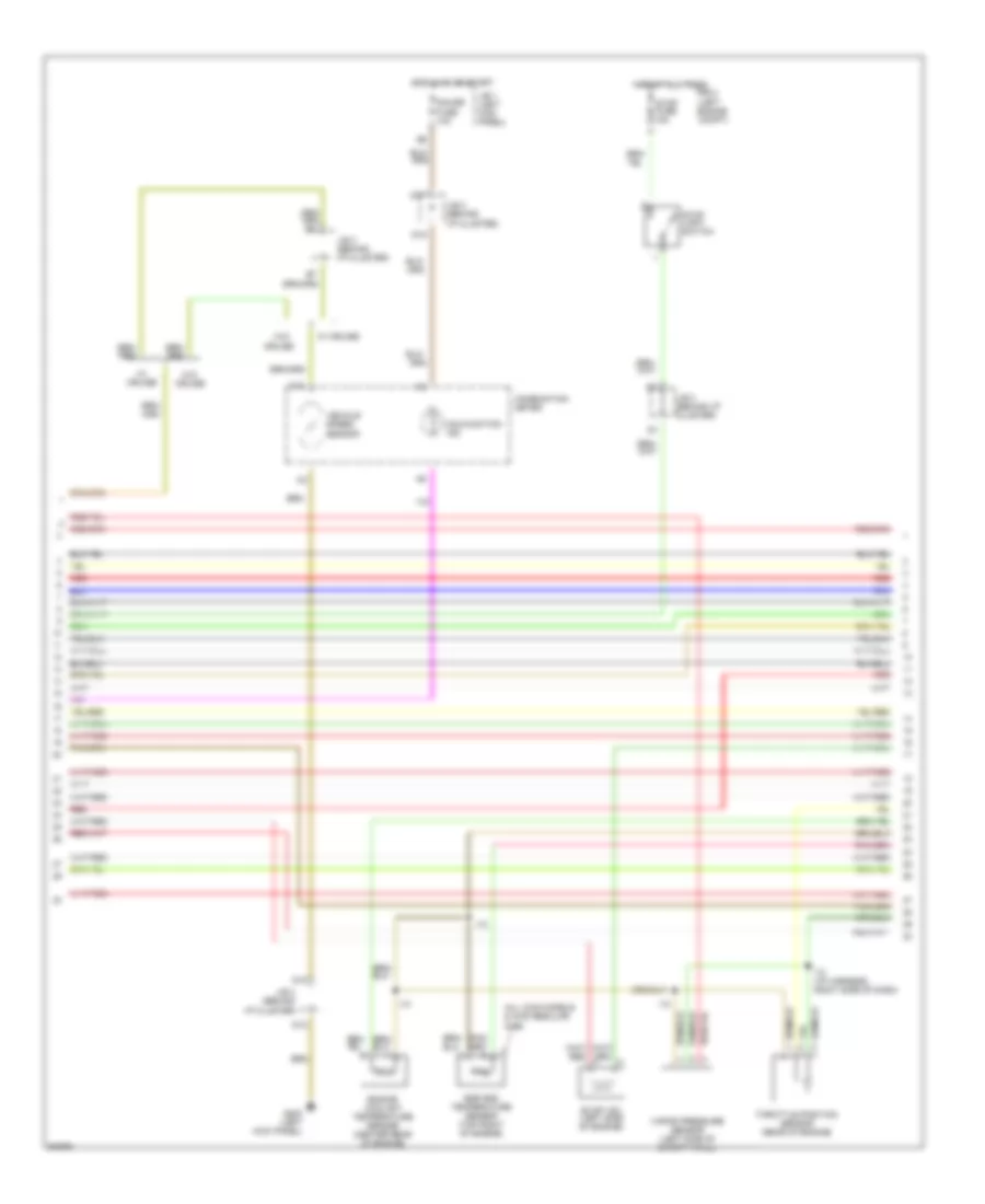
2.7L, Engine Performance Wiring Diagrams, A/T (2 of 3) for Toyota Tacoma SR5 1997
List of elements for 2.7L, Engine Performance Wiring Diagrams, A/T (2 of 3) for Toyota Tacoma SR5 1997:
- (behind i/p cluster) j/b 3
- (left side of dash) g202
- A/t oil temp ind.
- A12
- C10
- C11
- C12
- C13
- Combination meter
- D10
- D12
- D14
- D15
- D16
- D17
- D19
- Ect pwr ind.
- Egr gas temperature sensor (left rear of engine)
- Electronically controlled transmission pattern select switch
- Engine coolant temperature sensor (center rear of engine)
- Evap vsv (left side of engine compt)
- G200 (left kick panel)
- Gauge fuse 10a
- Hot at all times
- Hot in on or start
- Hot with tail relay energized
- I10
- I10 (i/p harness, right side of dash)
- J/b 1 (left kick panel)
- J/b 3 (behind i/p cluster)
- J/c 4 (left side of dash)
- Malfunction ind.
- O/d off ind.
- Panel fuse 10a
- Pnk
- R/b 2 (left engine compt)
- Red
- Speedo- meter
- Stop fuse 15a
- Stop light switch
- Throttle position sensor (throttle body)
- Vapor pressure sensor (left side of safety wall)
- W/ cruise
- W/ tach
- W/o cruise
- W/o tach
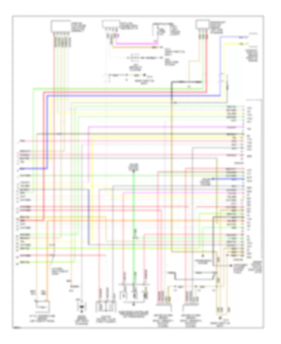
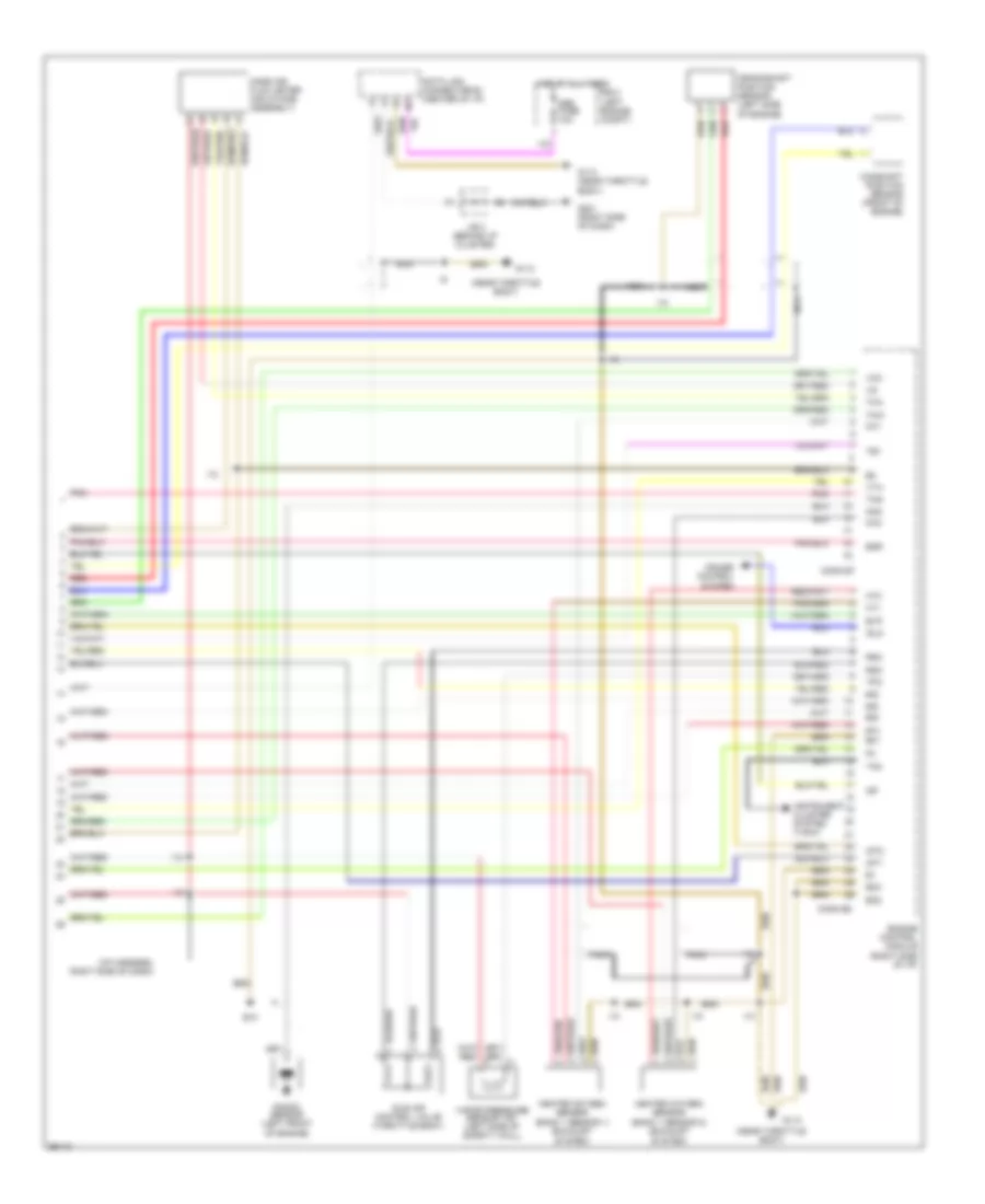
2.7L, Engine Performance Wiring Diagrams, A/T (3 of 3) for Toyota Tacoma SR5 1997
List of elements for 2.7L, Engine Performance Wiring Diagrams, A/T (3 of 3) for Toyota Tacoma SR5 1997:
- #10
- #20
- #30
- #40
- (i/p harn, right side of dash)
- (near throttle body)
- A/t oil temperature sensor (left side of trans)
- Camshaft position sensor (front of engine)
- Conn e7
- Conn e8
- Crankshaft position sensor (left side of engine)
- Cruise control system
- Data link connector #3 (center of i/p)
- E01
- E10
- Egr
- Electronic controlled transmission solenoid (on transmission)
- Engine control module (right side of i/p)
- Eo2
- Eo3
- Evp
- G113
- G113 (near throttle body)
- G201 (right side of dash)
- Heated oxygen sensor (bank 1 sensor 1) (exhaust system)
- Heated oxygen sensor (bank 1 sensor 2) (exhaust system)
- Hot at all times
- Ht1
- Ht2
- I10
- Idle air control valve (throttle body)
- Idlo
- Igf
- Igt1
- Igt2
- Instrument cluster system (tach)
- J/b 3 (behind i/p cluster)
- Knk
- Knock sensor (left front of engine)
- Mass air flow meter (air intake assembly)
- Nca
- Obd fuse 10a
- Oil
- Ox1
- Ox2
- Pnk
- R/b 2 (left engine compt)
- Red
- Rsc
- Rso
- Tac
- Te1
- Tha
- Thg
- Thw
- Transmission system
- Vcc
- Vta
2.7L, Engine Performance Wiring Diagrams, M/T (1 of 3) for Toyota Tacoma SR5 1997
List of elements for 2.7L, Engine Performance Wiring Diagrams, M/T (1 of 3) for Toyota Tacoma SR5 1997:
- (i/p harness, left end of dash)
- (i/p harness, right side of dash)
- (i/p harness, right side of dash) i10
- (ignition coil bracket)
- (left engine compt)
- (near throttle body)
- (right side of dash)
- (top left of battery) j/c 1
- 4wd
- Acc
- Acc st1
- Aci
- Act
- Air conditioning system
- Am1 fuse 40a
- Batt
- Circuit opening relay (behind left side of i/p)
- Conn e5
- Conn e6
- Data link connector #1 (left side of engine)
- E12
- E13
- E14
- E15
- Efi fuse 15a
- Efi relay
- Egr vsv (left side of engine)
- Engine control module (right side of i/p)
- F15
- Fuel injectors
- Fuel pump (in fuel tank)
- G102 (left front fender)
- G113
- G113 (near throttle body)
- G125
- G201
- G202 (left kick panel)
- Hot at all times
- Hot in on or start
- I10
- I10 (i/p harn, right side of dash)
- Ig2
- Ign fuse 7.5a
- Ignition coil and ignitor 1 (left front of eng)
- Ignition coil and ignitor 2 (left front of eng)
- Ignition switch
- J/b 1 (left kick panel)
- J/b 3 (center of i/p)
- Lock
- Ne-
- Noise filter (right side of eng compt)
- Ptnk
- R/b 2
- R/b 2 (left side of eng compt)
- Red
- Sdl
- Sp1
- Sta
- Sta fuse 7.5a
- Start
- Starter relay
- Starting/ charging system
- Transmission system
2.7L, Engine Performance Wiring Diagrams, M/T (2 of 3) for Toyota Tacoma SR5 1997
List of elements for 2.7L, Engine Performance Wiring Diagrams, M/T (2 of 3) for Toyota Tacoma SR5 1997:
- A5 a5 a5 a5 a5
- B5 b5 b5 b5 b5 b5
- C10
- Combination meter
- Cruise
- D10
- D12
- D17
- D19 d19 d19 d19 d19
- E6 e6 e6 e6 e6
- Egr gas temperature sensor (left rear of engine)
- Engine coolant temperature sensor (center rear of engine)
- Evap vsv (left side of engine compt)
- G200 (left kick panel)
- Gauge fuse 10a
- Hot at all times
- Hot in on or start
- I10
- I10 (i/p harness, right side of dash)
- J/b 1 j/b 1 j/b 1 j/b 1 j/b 1 (left (left (left (left (left kick kick kick kick kick panel) panel) panel) panel) panel)
- J/b 3 (behind i/p cluster)
- J/b 3 j/b 3 j/b 3 j/b 3 j/b 3 (behind (behind (behind (behind (behind i/p cluster) i/p cluster) i/p cluster) i/p cluster) i/p cluster)
- J/b 3 j/b 3 j/b 3 j/b 3 j/b 3 j/b 3 (behind i/p (behind i/p (behind i/p (behind i/p (behind i/p (behind i/p cluster) cluster) cluster) cluster) cluster) cluster)
- Malfunction ind.
- Pnk
- R/b 2 (left engine compt)
- Red
- Stop fuse 15a
- Stop light switch
- Throttle position sensor (throttle body) (throttle body) (throttle body) (throttle body) (throttle body) (throttle body)
- Vapor pressure sensor (left side of safety wall)
- Vehicle speed sensor
- W/ cruise
- W/o
- W/o cruise
2.7L, Engine Performance Wiring Diagrams, M/T (3 of 3) for Toyota Tacoma SR5 1997
List of elements for 2.7L, Engine Performance Wiring Diagrams, M/T (3 of 3) for Toyota Tacoma SR5 1997:
- #10
- #20
- #30
- #40
- (i/p harness, right side of dash)
- (near throttle body)
- Camshaft position sensor (front of engine)
- Conn e7
- Conn e8
- Crankshaft position sensor (left side of engine)
- Cruise control system
- Data link connector #3 (center of i/p)
- E01
- E10
- Egr
- Engine control module (right side of i/p)
- Eo2
- Eo3
- Evp
- G113
- G113 (near throttle body)
- G201 (right side of dash)
- Heated oxygen sensor (bank 1 sensor 1) (exhaust system)
- Heated oxygen sensor (bank 1 sensor 2) (exhaust system)
- Hot at all times
- Ht1
- Ht2
- I10
- Idle air control valve (throttle body)
- Idlo
- Igf
- Igt1
- Igt2
- Instrument cluster system (tach)
- J/b 3 (behind i/p cluster)
- Knk
- Knock sensor (left front of engine)
- Mass air flow meter (air intake assembly)
- Nca
- Obd fuse 10a
- Ox1
- Ox2
- Pnk
- R/b 2 (left engine compt)
- Red
- Rsc
- Rso
- Tac
- Te1
- Tha
- Thg
- Thw
- Tpc
- Vapor pressure sensor vsv (left side of safety wall)
- Vcc
- Vta
3.4L
3.4L, Engine Performance Wiring Diagrams, A/T (1 of 3) for Toyota Tacoma SR5 1997
List of elements for 3.4L, Engine Performance Wiring Diagrams, A/T (1 of 3) for Toyota Tacoma SR5 1997:
- (floor a/t)
- (i/p harn, right side of dash)
- (left engine compt)
- (left front fender)
- (left side of engine)
- (right side of dash)
- (right side of engine compartment)
- (top left of battery) j/c 1
- 4wd
- Ac1
- Acc
- Acc st1
- Act
- Air conditioning
- Am1 fuse 40a
- Batt
- Circuit opening relay (behind left side of i/p)
- Conn e5
- Conn e6
- Cruise control system
- Data link connector #1 (left side of engine)
- E12
- E13
- E14
- E15
- E3 (eng harn, rear of left front fender)
- Efi fuse 15a
- Efi relay
- Egr
- Egr vsv (left side of engine)
- Engine control module (right side of i/p)
- Evp1
- F15
- Floor a/t
- Fuel injectors
- Fuel pump (in fuel tank)
- G102
- G112
- G112 (left side of engine)
- G201
- G202 (left kick panel)
- Hot at all times
- Hot in on or start
- I10
- I10 (i/p harn, right side of dash)
- Idlo
- Ig2
- Ign fuse 7.5a
- Igniter
- Ignition coil no. 1 (top right side of engine)
- Ignition coil no. 2 (top right side of engine)
- Ignition coil no. 3 (top right side of engine)
- Ignition switch
- Instrument cluster system (tachometer)
- J/b 1 (left kick panel)
- J/b 3 (center of i/p)
- Lock
- Od1
- Od2
- Oil -w
- Pnk
- Pwr
- R/b 2
- R/b 2 (left side of eng compt)
- Red
- Sdl
- Sp1
- Sta fuse 7.5a
- Start
- Starter relay
- Starting
- System
- Te1
- Tfn
- Tpc
- Transmission system
- Vapor pressure sensor vsv (left side of safety wall)
3.4L, Engine Performance Wiring Diagrams, A/T (2 of 3) for Toyota Tacoma SR5 1997
List of elements for 3.4L, Engine Performance Wiring Diagrams, A/T (2 of 3) for Toyota Tacoma SR5 1997:
- (all 2wd models & 4wd reg cab)
- (at left kick panel)
- (center of i/p)
- (column a/t)
- (floor a/t)
- (left side
- (w/ tach) (w/o tach)
- A/t indicator switch (on transmission)
- A/t oil temp ind.
- A12
- B4 (column a/t)
- B5 (column a/t)
- C10
- C11
- C13
- Cig fuse 15a
- Column a/t
- Combination meter
- Cruise
- D ind.
- D n
- D1 a5
- D10
- D12
- D14
- D15 d19
- D16
- D17
- Ect pwr
- Egr gas temperature sensor (top center of engine)
- Electronically controlled transmission pattern select switch
- Engine coolant temperature sensor (center rear of engine)
- Evap vsv (left side of engine)
- F19
- F20
- Floor a/t
- G200
- Gauge fuse 10a
- Hot in acc or on
- Hot in on or start
- I10
- I10 (i/p harn, right side of dash)
- Ind.
- J/b 1 (left kick panel)
- J/b 3
- J/b 3 (behind i/p cluster)
- J/b 3 (center of i/p)
- J/c 4
- J/c 4 (left side of dash)
- J/c 4 (left side of i/p)
- J/c 8 (right side of dash)
- L ind.
- Malf. ind. lamp
- N ind.
- Norm
- O/d ind lamp
- O/d main switch
- Of i/p)
- Pnk
- Pwr
- R ind.
- Throttle position sensor (rear of engine)
- Vehicle speed sensor
- W/ column a/t
- W/ cruise
- W/ floor a/t
- W/o
- W/o cruise
- P ind.
3.4L, Engine Performance Wiring Diagrams, A/T (3 of 3) for Toyota Tacoma SR5 1997
List of elements for 3.4L, Engine Performance Wiring Diagrams, A/T (3 of 3) for Toyota Tacoma SR5 1997:
- #10
- #20
- #30
- #40
- #50
- #60
- (center of i/p)
- (i/p harn, right side dash)
- (i/p harn, right side of dash)
- (i/p harness, right side of dash)
- (left front of engine)
- (left side of eng)
- A/t oil temperature sensor (center rear of engine compt)
- Camshaft position sensor (front of engine)
- Conn e7
- Conn e8
- Crankshaft position sensor (front of engine)
- Cruise control system
- E01
- E02
- E03
- E10
- Electronic controlled transmission solenoid (on transmission)
- Engine control module (right side of i/p)
- G110
- G112
- G112 (left side of engine)
- G201 (right kick panel)
- Heated oxygen sensor (bank 1 sensor 1) (bottom left of vehicle)
- Heated oxygen sensor (bank 1 sensor 2) (bottom left of vehicle)
- Hot at all times
- Ht1
- Ht2
- I10
- Idle air control valve (top left side of engine)
- Igf
- Igt1
- Igt2
- Igt3
- J/b 3
- Knk1
- Knk2
- Knock sensor 1 (left front of engine)
- Knock sensor 2 (left front of engine)
- Mass air mass air flow meter flow meter (right side (right side of engine of engine compartment) compartment)
- Nca
- Ne-
- Nsw
- Obd fuse 10a
- Oil
- Ox1
- Ox2
- Ptnk
- R/b 2 (left engine compt)
- Red
- Rsc
- Rso
- Sp2+
- Sp2-
- Sta
- Stop fuse 15a
- Stop light switch
- Tha
- Thg
- Thw
- Transmission system
- Vapor pressure sensor (left side of safety wall)
- Vcc
- Vehicle speed sensor (on trans- mission)
- Vta
3.4L, Engine Performance Wiring Diagrams, M/T (1 of 3) for Toyota Tacoma SR5 1997
List of elements for 3.4L, Engine Performance Wiring Diagrams, M/T (1 of 3) for Toyota Tacoma SR5 1997:
- (i/p harn, right side of dash)
- (i/p harness, right side of dash)
- (i/p harness, right side of dash) i10
- (left engine compt)
- (left side of engine)
- (right side of dash)
- (right side of engine compartment)
- (top left of battery) j/c 1
- 4wd
- Acc
- Acc st1
- Aci
- Act
- Air conditioning system
- Am1 fuse 40a
- Batt
- Circuit opening relay (behind left side of i/p)
- Conn e5
- Conn e6
- Data link connector #1 (left side of engine)
- E03
- E12
- E13
- E14
- E15
- Efi fuse 15a
- Efi relay
- Egr vsv (left side of engine)
- Engine control module (right side of i/p)
- F15
- Fuel injectors
- Fuel pump (in fuel tank)
- G102 (left front fender)
- G110 (left front of engine)
- G112
- G201
- G202 (left kick panel)
- Hot at all times
- Hot in on or start
- Ht1
- Ht2
- I10
- Ig2
- Ign fuse 7.5a
- Igniter
- Ignition coil no. 1 (top right side of engine)
- Ignition coil no. 2 (top right side of engine)
- Ignition coil no. 3 (top right side of engine)
- Ignition switch
- Instrument cluster system (tachometer)
- J/b 1 (left kick panel)
- J/b 3 (center of i/p)
- Lock
- Ne-
- Ptnk
- R/b 2
- R/b 2 (left side of eng compt)
- Red
- Sdl
- Sp1
- Sta
- Sta fuse 7.5a
- Start
- Starter relay
- Starting/ charging system
- Transmission system
3.4L, Engine Performance Wiring Diagrams, M/T (2 of 3) for Toyota Tacoma SR5 1997
List of elements for 3.4L, Engine Performance Wiring Diagrams, M/T (2 of 3) for Toyota Tacoma SR5 1997:
- (all 2wd models & 4wd regular cab)
- C10
- Combination meter
- Cruise
- D10
- D12
- D17
- D19
- Egr gas temperature sensor (top right of engine)
- Engine coolant temperature sensor (center rear of engine)
- Evap vsv (left side of engine)
- G200 (left kick panel)
- Gauge fuse 10a
- Hot at all times
- Hot in on or start
- I10
- I10 (i/p harness, right side of dash)
- J/b 1 (left kick panel)
- J/b 3 (behind i/p cluster)
- Malfunction ind.
- R/b 2 (left engine compt)
- Red
- Stop fuse 15a
- Stop light switch
- Throttle position sensor (rear of engine)
- Vapor pressure sensor (left side of safety wall)
- Vehicle speed sensor
- W/ cruise
- W/o
- W/o cruise
3.4L, Engine Performance Wiring Diagrams, M/T (3 of 3) for Toyota Tacoma SR5 1997
List of elements for 3.4L, Engine Performance Wiring Diagrams, M/T (3 of 3) for Toyota Tacoma SR5 1997:
- #10
- #20
- #30
- #40
- #50
- #60
- (i/p harn, right side of dash)
- (i/p harness, right side of dash)
- (left front of engine)
- (left side of engine)
- Camshaft position sensor (front of engine)
- Conn e7
- Conn e8
- Crankshaft position sensor (front of engine)
- Cruise control system
- Data link connector #3 (center of i/p)
- E01
- E10
- Egr
- Engine control module (right side of i/p)
- Evp1
- G110
- G112
- G112 (left side of engine)
- G201 (right side of dash)
- Heated oxygen sensor (bank 1 sensor 1) (bottom left of vehicle)
- Heated oxygen sensor (bank 1 sensor 2) (bottom left of vehicle)
- Hot at all times
- I10
- Idle air control valve (top left side of engine)
- Idlo
- Igf
- Igt1
- Igt2
- Igt3
- J/b 3 (behind i/p cluster)
- Knk1
- Knk2
- Knock sensor 1 (left front of engine)
- Knock sensor 2 (left front of engine)
- Mass air flow meter (right side of engine compartment)
- Nca
- Obd fuse 10a
- Ox1
- Ox2
- R/b 2 (left engine compt)
- Red
- Rsc
- Rso
- Te1
- Tha
- Thg
- Thw
- Tpc
- Vapor pressure sensor vsv (left side of engine)
- Vcc
- Vta