ANTI-LOCK BRAKES
Anti-lock Brakes Wiring Diagram, with VSC (1 of 2) for Toyota Camry SE 2005

List of elements for Anti-lock Brakes Wiring Diagram, with VSC (1 of 2) for Toyota Camry SE 2005:
- (at left kick panel) ii
- (behind right side of dash) engine control module
- (right front of engine compt) ea
- +bs
- 2.4l
- 3.0l
- Abs 1 fuse 50a
- Abs 3 fuse 30a
- Abs cut relay
- Abs mtr relay
- Abs r/b (on left front corner of engine compt)
- B30
- B70
- Brl
- Canh
- Canl
- Computer data lines system
- Csw
- D/g
- Driver side j/b (behind left side of dash)
- E3 (2.4l japan production)
- Eb (right front of engine compt)
- Ed (at front of left front fender)
- Eng+
- Eng-
- Engine room j/b (on left side of engine compt)
- Engine room r/b (on left side of engine compt)
- Fl+
- Fl-
- Fr+
- Fr-
- G11
- G23
- Gnd1
- Gnd2
- Hot at all times
- Hot in on or start
- Ig1
- Ig2 fuse 10a
- Im (at right dash reinforcement)
- Ind
- J/c 22 & 23 (left side of dash)
- J22
- J23
- Left front abs speed sensor (mounted on left front wheel hub assembly)
- Left rear abs speed sensor
- Lever type
- Mrf
- Nca
- Neo
- Parking brake switch (on parking brake pedal assembly)
- Passenger side j/b (behind right center of dash)
- Pedal type
- Pkb
- Pnk
- Red
- Right front abs speed sensor (mounted on right front wheel hub assembly)
- Right rear abs speed sensor
- Rl+
- Rl-
- Rr+
- Rr-
- Skid control ecu with actuator (at right side of engine compt)
- Sp1
- Stp
- Trac off switch
- Trc+
- Trc-
- Us built
- Vscw
- Wfse
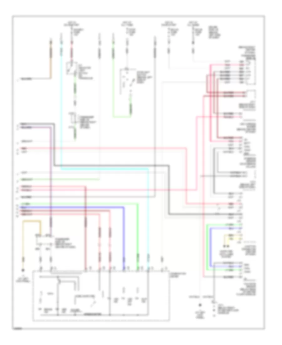
Anti-lock Brakes Wiring Diagram, with VSC (2 of 2) for Toyota Camry SE 2005
List of elements for Anti-lock Brakes Wiring Diagram, with VSC (2 of 2) for Toyota Camry SE 2005:
- (at left kick panel)
- (behind right center of dash)
- 2.4l
- A/t indicator light switch (on transaxle)
- A120
- A66
- A76
- A96
- Abs ind
- B27
- B28
- B29
- B68
- B74
- B76
- B84
- B86
- Batt
- Brake ind
- Canh
- Canl
- Column)
- Combination meter
- Computer data lines system
- Driver side j/b (behind left side of dash)
- Ecu-b fuse 10a
- Ecu-ig fuse 10a
- Ess
- G13
- G19
- G21
- Gauge 2 fuse 10a
- Gnd
- Hot at all times
- Hot in on or start
- Ig1
- Ii (at left kick panel)
- J/c 2 (behind left side of dash)
- J/c 4 (below front of center floor console)
- J/c 7 (behind right side of dash)
- J13
- J14
- J15
- J16
- J17
- Junction connector (center of dash)
- Micro computer
- Passenger side j/b
- Passenger side j/b (behind right center of dash)
- Pnk
- Power
- Red
- Slip ind
- Speedometer
- Steering sensor (on steering
- Stop fuse 15a
- Stoplight switch (behind left side of dash)
- Vsc ind
- Vsc off ind
- Vsc warning buzzer (behind center of dash)
- Yaw rate sensor (below rear of center floor console)
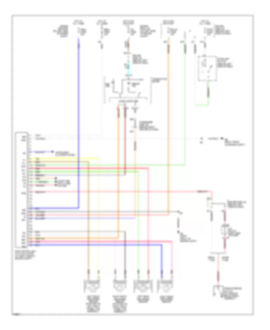
Anti-lock Brakes Wiring Diagram, without VSC, Japan Production for Toyota Camry SE 2005
List of elements for Anti-lock Brakes Wiring Diagram, without VSC, Japan Production for Toyota Camry SE 2005:
- +bm
- +bs
- Abs 1 fuse 50a
- Abs 2 fuse 40a
- Abs ind
- B74
- B84
- Brake ind
- Brl
- Combination meter
- Computer data lines system
- D/g
- Driver side j/b (behind left side of dash)
- Ea (right front of engine compt)
- Eb (right front of engine compt)
- Ecu-ig fuse 10a
- Engine room j/b (on left side of engine compt)
- Engine room r/b (on left side of engine compt)
- Fl+
- Fl-
- Fr+
- Fr-
- G11
- G13
- G19
- G21
- G23
- Gnd
- Hot at all times
- Hot in on or start
- Ig2 fuse 10a
- Instrument cluster system
- J/c 22 & 23 (left side of dash)
- J22
- J23
- Left front abs speed sensor (mounted on left front wheel hub assembly)
- Left rear abs speed sensor
- Lever type
- Micro computer
- Parking brake switch (on parking brake pedal assembly)
- Passenger side j/b (behind right center of dash)
- Pedal type
- Pkb
- Pnk
- Red
- Right front abs speed sensor (mounted on right front wheel hub assembly)
- Right rear abs speed sensor
- Rl+
- Rl-
- Rr+
- Rr-
- Skid control ecu with actuator (at right side of engine compt)
- Sp1
- Stop fuse 15a
- Stoplight switch (behind left side of dash)
- Stp
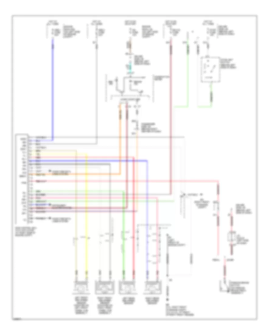
Anti-lock Brakes Wiring Diagram, without VSC, USA Production for Toyota Camry SE 2005
List of elements for Anti-lock Brakes Wiring Diagram, without VSC, USA Production for Toyota Camry SE 2005:
- +bm
- +bs
- Abs 1 fuse 50a
- Abs 3 fuse 30a
- Abs ind
- B74
- B84
- Brake ind
- Combination meter
- Computer data lines system
- D/g
- Driver side j/b (behind left side of dash)
- E3 (left front of engine compt)
- Ea (right front of engine compt)
- Eb (2.4l: right front of engine compt) (3.0l & 3.3l: at front of right front fender)
- Ebdw
- Ecu-ig fuse 10a
- Engine room j/b (on left side of engine compt)
- Engine room r/b (on left side of engine compt)
- Fl+
- Fl-
- Fr+
- Fr-
- G11
- G13
- G19
- G21
- G23
- Gnd1
- Gnd2
- Hot at all times
- Hot in on or start
- Ig1
- Ig2 fuse 10a
- Instrument cluster system
- J/c 22 & 23 (left side of dash) j23
- J22
- Left front abs speed sensor (mounted on left front wheel hub assembly)
- Left rear abs speed sensor
- Lever
- Micro computer
- Parking brake switch (on parking brake pedal assembly)
- Passenger side j/b (behind right center of dash)
- Pedal
- Pkb
- Pnk
- Red
- Right front abs speed sensor (mounted on right front wheel hub assembly)
- Right rear abs speed sensor
- Rl+
- Rl-
- Rr+
- Rr-
- Skid control ecu with actuator (at right side of engine compt)
- Sp1
- Stop fuse 15a
- Stoplight switch (behind left side of dash)
- Stp