ANTI-LOCK BRAKES
Anti-lock Brake Wiring Diagrams for Toyota Celica GT 1999
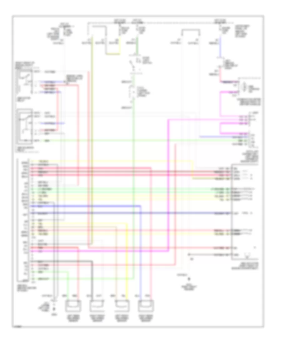
List of elements for Anti-lock Brake Wiring Diagrams for Toyota Celica GT 1999:
- (engine harn, above grille opening) e1
- (right front of engine compt) r/b 5
- A10
- A11
- Abs actuator (right front of engine compartment)
- Abs ecu (behind center of dash)
- Abs fuse 50a
- Abs motor relay
- Abs solenoid relay
- Abs warning ind
- Ast
- B11
- C10
- Combination meter (behind front of center console)
- Data link connector 1 (left rear corner of engine compt)
- Ecu-ig fuse 15a
- F11
- Fl+
- Fl-
- Fr+
- Fr-
- G101 (right front fender)
- G200
- Gauge fuse 10a
- Gnd
- Grd
- Hot at all times
- Hot in on or start
- Ig1
- Instrument panel j/b (behind left side of dash)
- J/b 3 (behind center of dash)
- J/c 1 (upper left kick panel)
- J/c 2 (upper left kick panel)
- J/c 7
- Left front abs speed sensor
- Left rear abs speed sensor
- Pnk
- R/b 2 & j/b 2 (left side of engine compt)
- Red
- Right front abs speed sensor
- Right rear abs speed sensor
- Rl+
- Rl-
- Rr+
- Rr-
- Sflh
- Sflr
- Sfrh
- Sfrr
- Srlh
- Srlr
- Srrh
- Srrr
- Stop fuse 15a
- Stop- light switch
- Stp
 English