ANTI-LOCK BRAKES
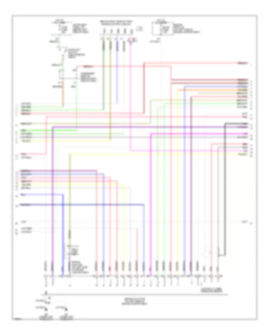
Anti-lock Brakes Wiring Diagram, with VSC (1 of 3) for Toyota Highlander Limited 2003

List of elements for Anti-lock Brakes Wiring Diagram, with VSC (1 of 3) for Toyota Highlander Limited 2003:
- (2wd) slip ind
- +bi
- +bo
- A12
- Abs 1 fuse 40a
- Abs 2 fuse 40a
- Abs r/b (on left rear of engine compt)
- Abs sol relay
- Brake ind
- Brake warning switch (on master cylinder assembly)
- Brl
- C11
- C12
- Combination meter
- Data link connector (dcl) 3 (under left side of dash)
- Eb (at right front fender apron)
- Eng+
- Engine room r/b (on left side of engine compt)
- Fl+
- Fl-
- Fr+
- Fr-
- Fusible link block (on left side of engine compt)
- Gnd1
- Gnd2
- Hot at all times
- Hot in on or start
- Ig1
- Ign fuse 7.5a
- Ind
- Ind abs
- Ind vsc
- Instrument panel j/b (behind left side of dash)
- J/c 6 (left side of dash, behind instrument cluster)
- Junction connector 4 (on right side of engine compartment)
- Lbl
- Left front abs speed sensor (at left front wheel)
- Left rear abs speed sensor (at left rear wheel)
- Mr2
- Parking brake switch (at base of parking brake pedal)
- Passenger side j/b (behind right side of dash)
- Passenger side j/b (behind right side of dash)
- Pkb
- Pnk
- R1+
- R2+
- Right front abs speed sensor (at right front wheel)
- Right rear abs speed sensor (at right rear wheel)
- Rl+
- Rl-
- Rr+
- Rr-
- S11
- S12
- Sflh
- Sflr
- Sil
- Skid control ecu (above instrument panel j/b)
- Skid control relay
- Sp1
- Src1
- Src2
- Srm1
- Srm2
- Srrh
- Srrr
- Stp
- Trac off ind
- Trc+
- Trc-
- Vscw
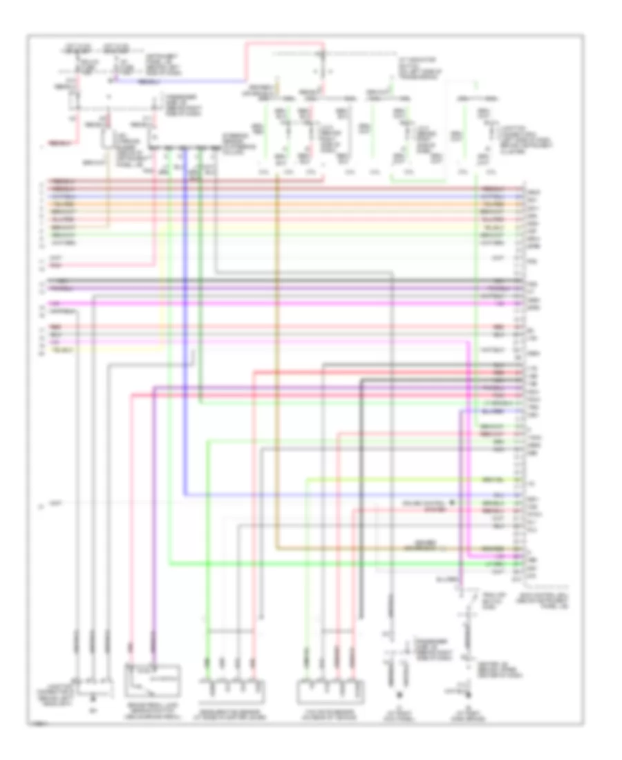
Anti-lock Brakes Wiring Diagram, with VSC (2 of 3) for Toyota Highlander Limited 2003
List of elements for Anti-lock Brakes Wiring Diagram, with VSC (2 of 3) for Toyota Highlander Limited 2003:
- (behind right side of dash) engine control module
- 2.4l
- 3.0l
- A11
- Abs 3 fuse 7.5a
- Brake actuator (on left rear of engine compartment)
- E5 e6
- Ecu-b fuse 7.5a
- Eg (under left headlight)
- Eh (under left headlight)
- Eng+
- Engine room j/b (on left side of engine compartment)
- Engine room r/b (on left side of engine compartment)
- Hot at all times
- Instrument panel j/b (behind left side of dash)
- Master cylinder pressure sensor
- Nca
- Neo
- Passenger side j/b (behind right side of dash)
- Pnk
- Red
- Stop fuse 20a
- Stoplight switch (above brake pedal)
- Trc+
- Trc-
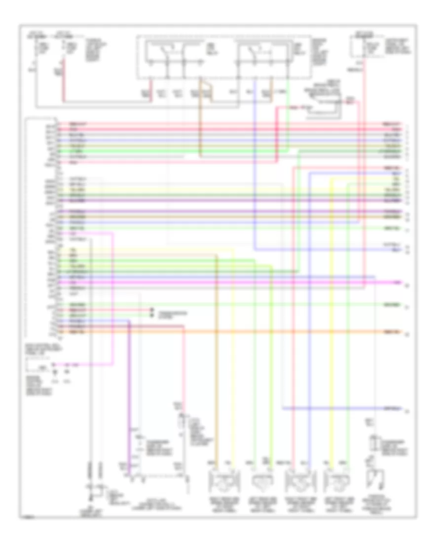
Anti-lock Brakes Wiring Diagram, with VSC (3 of 3) for Toyota Highlander Limited 2003
List of elements for Anti-lock Brakes Wiring Diagram, with VSC (3 of 3) for Toyota Highlander Limited 2003:
- 2.4l
- 3.0l
- A/t indicator switch (on left side of transmission)
- Ast
- Bat
- Brake pedal load sensing switch (above brake pedal)
- C11
- Ccs
- Center j/b (behind upper center of dash)
- Cruise control system
- Csw
- D/g
- D10
- Deceleration sensor (at base of shifter lever)
- Ecu-ig fuse 15a
- Ess
- Fss
- Fsw+
- Fsw-
- Ggnd
- Gl1
- Gl2
- Gnd3
- Gnd4
- Gss
- Gyaw
- Hot in on or start
- Ib (at right dash brace)
- Ic (at right kick panel)
- Ig1 fuse 7.5a
- Instrument panel j/b (behind left side of dash)
- J/c 8 (behind right side of dash)
- Junction connector 2 (behind left headlight)
- Junction connector 6 (left side of dash behind instrument cluster)
- Nca
- Neo
- Passenger side j/b (behind right side of dash)
- Pmc
- Pnk
- Red
- S10
- Sfrh
- Sfrr
- Skid control ecu (above instrument panel j/b)
- Sm1+
- Sm1-
- Sm2+
- Sm2-
- Srlh
- Srlr
- Ss1+
- Ss1-
- Steering sensor (in steering column)
- Trac off switch (2wd)
- Trig
- Vcm
- Vgs
- Vsc warning buzzer (above of instrument panel j/b)
- Vys
- Yaw rate sensor (on rear of vehicle)
- Yaw2
- Yss
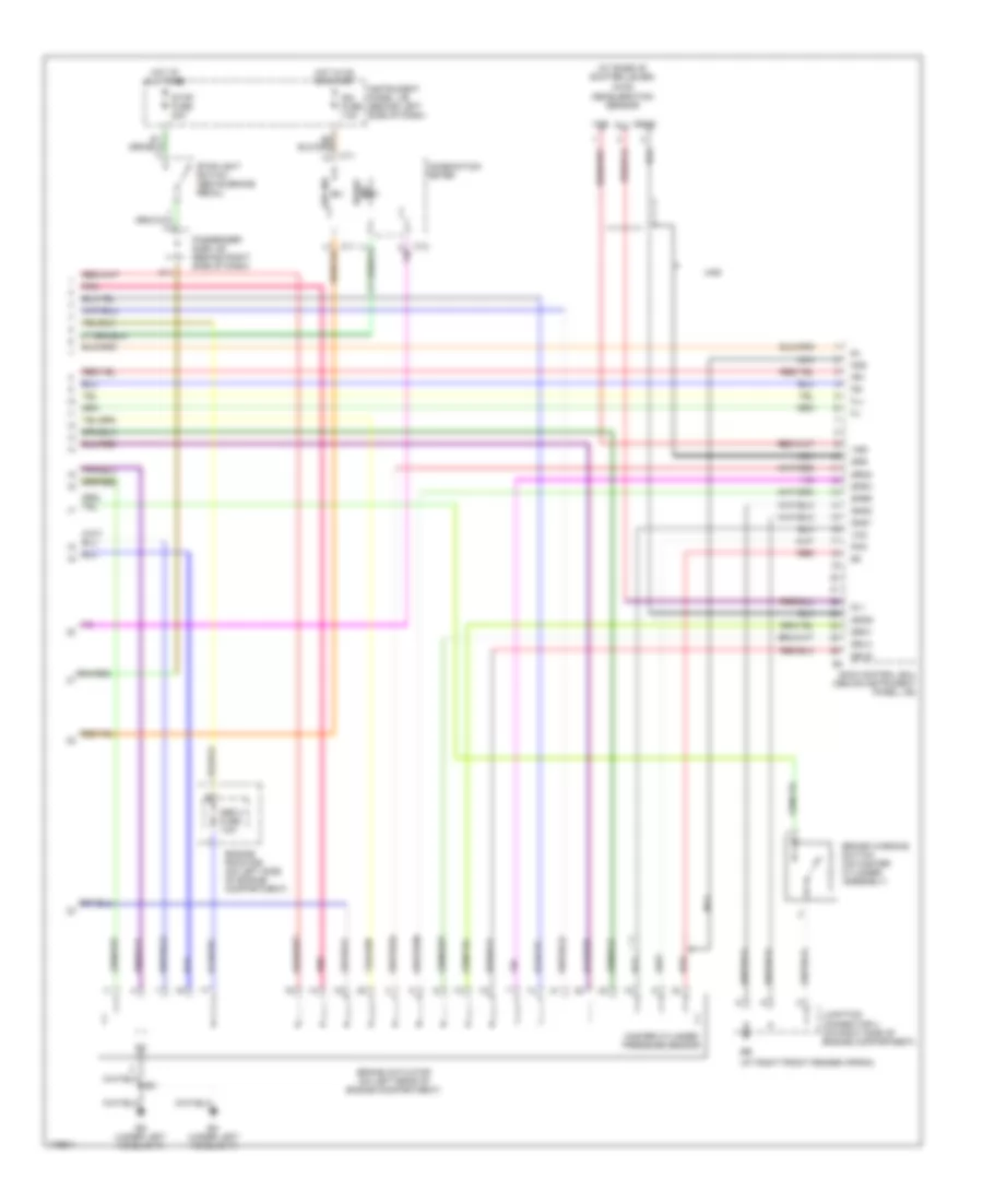
Anti-lock Brakes Wiring Diagram, without VSC (1 of 2) for Toyota Highlander Limited 2003
List of elements for Anti-lock Brakes Wiring Diagram, without VSC (1 of 2) for Toyota Highlander Limited 2003:
- (above brake pedal)
- 2.4l
- 3.0l
- A12
- Abs 1 fuse 40a
- Abs 2 fuse 40a
- Abs mtr relay
- Abs sol relay
- Ast
- Brake pedal load sensing switch
- Brl
- D/g
- D10
- Data link connector (dcl) 3 (under left side of dash)
- Ecu-ig fuse 15a
- Eh (under left headlight)
- Engine control module (behind right side of dash)
- Engine room r/b (on left side of engine compt)
- Fsw+
- Fsw-
- Fusible link block (on left side of engine compt)
- Gnd3
- Gnd4
- Hot at all times
- Hot in on or start
- Ig1
- Instrument panel j/b (behind left side of dash)
- J/c 2 (behind left headlight)
- J/c 6 (left side of dash, behind instrument cluster)
- Lbl
- Left front abs speed sensor (at left front wheel)
- Left rear abs speed sensor (at left rear wheel)
- Mrf
- Neo
- Parking brake switch (at base of parking brake pedal)
- Passenger side j/b (behind right side of dash)
- Pkb
- Pnk
- Right front abs speed sensor (at right front wheel)
- Right rear abs speed sensor (at right rear wheel)
- Rl+
- Rl-
- Rr+
- Rr-
- Sflh
- Sflr
- Sil
- Skid control ecu (above instrument panel j/b)
- Sm1+
- Sm1-
- Sm2+
- Sm2-
- Sp1
- Srrh
- Srrr
- Stp
- Transmissions system
Anti-lock Brakes Wiring Diagram, without VSC (2 of 2) for Toyota Highlander Limited 2003
List of elements for Anti-lock Brakes Wiring Diagram, without VSC (2 of 2) for Toyota Highlander Limited 2003:
- (4wd) deceleration sensor
- (at base of shifter lever)
- (at right front fender apron)
- 4wd
- A11
- Abs 3 fuse 7.5a
- Abs ind
- Brake
- Brake actuator (on left rear of engine compartment)
- Brake warning switch (on master cylinder assembly)
- C11
- C12
- Combination meter
- Eg (under left headlight)
- Eh (under left headlight)
- Engine room r/b (on left side of engine compartment)
- Fl+
- Fl-
- Fr+
- Fr-
- Fss
- Ggnd
- Gl1
- Gnd1
- Gnd2
- Gss
- Hot at all times
- Hot in on or start
- Ign fuse 7.5a
- Ind
- Instrument panel j/b (behind left side of dash)
- Junction connector 4 (on right side of engine compartment)
- Master cylinder pressure sensor
- Nca
- Passenger side j/b (behind right side of dash)
- Pmc
- Pnk
- Red
- Sfrh
- Sfrr
- Skid control ecu (above instrument panel j/b)
- Srlh
- Srlr
- Srm1
- Srm2
- Stop fuse 20a
- Stoplight switch (above brake pedal)
- Vcm
- Vgs