ANTI-LOCK BRAKES
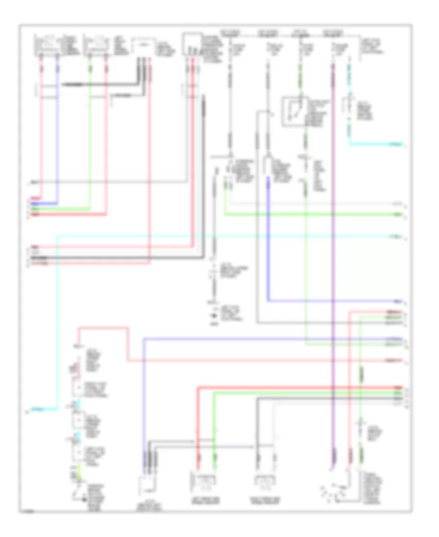
Anti-lock Brake Wiring Diagrams, with VSC (1 of 3) for Toyota Land Cruiser 2001

List of elements for Anti-lock Brake Wiring Diagrams, with VSC (1 of 3) for Toyota Land Cruiser 2001:
- (engine harn, left rear corner of engine compt) e14
- A37
- A38
- A39
- A40
- A41
- A44
- Abs & ba & trac & vsc actuator
- Abs & ba & trac & vsc ecu (behind left side of dash)
- Abs 1 fuse 50a
- Abs 2 fuse 40a
- Abs mtr 1 relay
- Abs mtr 2 relay
- Abs sol relay
- Ast
- B10
- B11
- B12
- B14
- Braided
- E13
- E13 (engine harn, left fender apron)
- Engine controls system
- Engine room j/b (on left inner fender panel)
- Fl+
- Fl-
- Fr+
- Fr-
- Fss
- G103 (right front fender apron)
- Gnd1
- Gnd2
- Hot at all times
- Hot in run or start
- I2 (dash harn, left end of dash)
- Ig2
- Ign fuse 10a
- Left kick panel j/b (at left kick panel)
- Mr1
- Mr2
- Mss
- Mt+
- Mt-
- Mtt
- P10
- Pmc
- Pnk
- R1+
- R2+
- Red
- Sa1
- Sa2
- Sa3
- Sflh
- Sflr
- Sfrh
- Sfrr
- Srlh
- Srlr
- Srrh
- Srrr
- Str
- Vcm
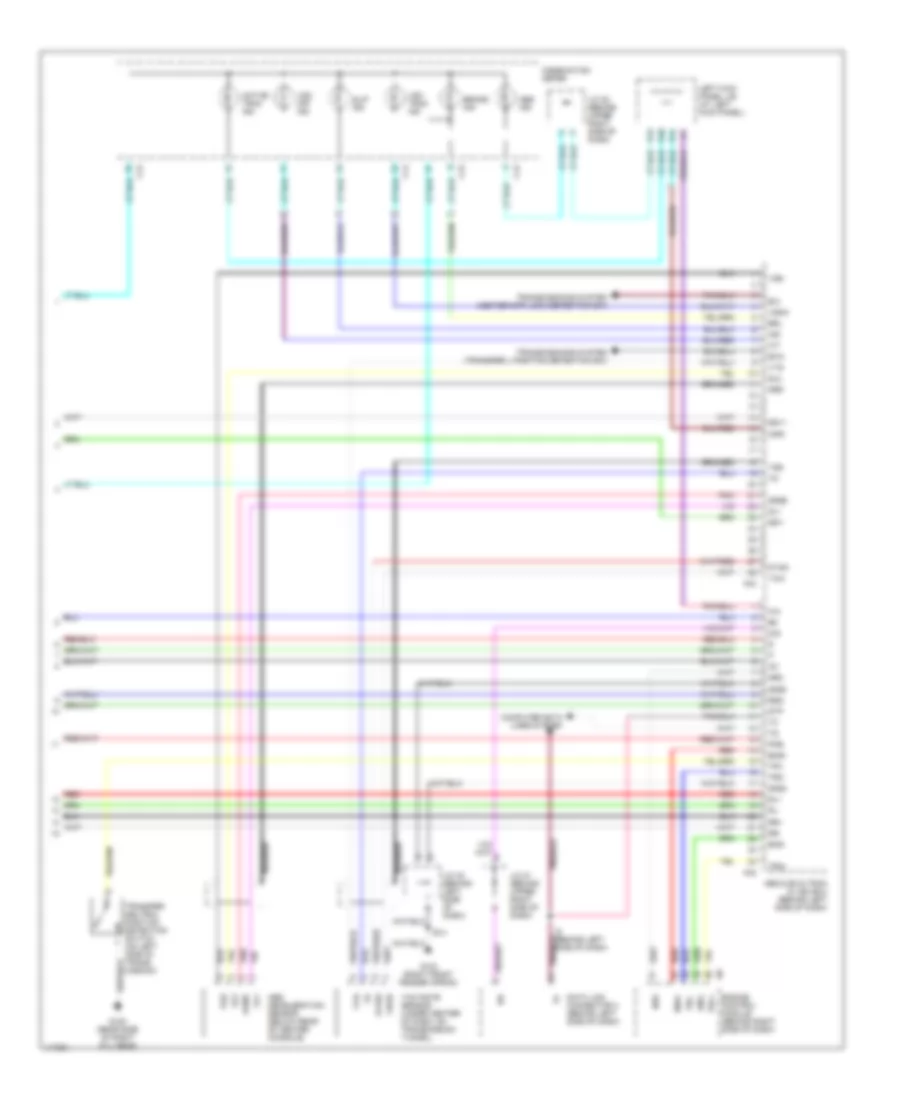
Anti-lock Brake Wiring Diagrams, with VSC (2 of 3) for Toyota Land Cruiser 2001
List of elements for Anti-lock Brake Wiring Diagrams, with VSC (2 of 3) for Toyota Land Cruiser 2001:
- Ahc-ig fuse 20a
- B10
- Braided
- Ecu-ig fuse 15a
- G200
- Gauge fuse 15a
- Hot at all times
- Hot in run or start
- I34
- J/c 14 (behind upper center of dash)
- J/c 19 (behind upper right side of dash)
- J/c 23 (behind glove box)
- J/c 42 (behind left side of dash)
- J/c 44 (behind upper right side of dash)
- Left front abs speed sensor
- Left kick panel j/b (at left kick panel)
- Left rear abs speed sensor
- Master cylinder pressure sensor (on brake master cylinder)
- N15
- O12
- P83
- Park/ neutral position switch (on left side of trans- mission)
- Parking brake switch (on base of park brake lever)
- Pmc
- Pnk
- Red
- Right front abs speed sensor
- Right kick panel j/b (at right kick panel)
- Right rear abs speed sensor
- Rss
- Ss1+
- Ss1-
- Steering angle sensor (behind left side of dash)
- Stop fuse 15a
- Stoplight switch (on bracket, above brake pedal)
- Vcm
- Vsc warning buzzer (behind left side of dash)
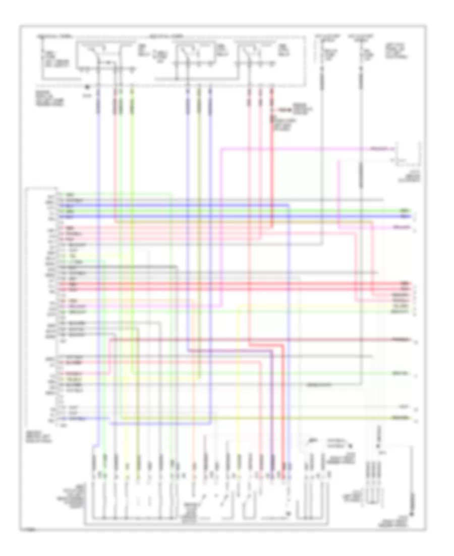
Anti-lock Brake Wiring Diagrams, with VSC (3 of 3) for Toyota Land Cruiser 2001
List of elements for Anti-lock Brake Wiring Diagrams, with VSC (3 of 3) for Toyota Land Cruiser 2001:
- A42
- A43
- Abs & ba & trac & vsc ecu (behind left side of dash)
- Abs deceleration sensor (below rear of center console)
- Abs ind
- Active trac ind
- Braided
- Brake ind
- Brl
- C12
- C14
- C15
- Combination meter
- Computer data lines system
- D/g
- Data link connector 3 (behind left side of dash)
- E14
- Eng+
- Eng-
- Engine control module (behind right side of dash)
- Exi
- Exi3
- G103 (right front fender apron)
- G120 (rear side of right cyl head)
- Ggnd
- Gl1
- Gl2
- Gnd3
- Gnd4
- Gss
- Gyaw
- I5 (behind left side of dash)
- Ig1
- Ind
- Infr
- J/c 21 (behind upper right side of dash)
- J/c 28 (behind upper right side of dash)
- J/c 42 (behind left side of dash)
- Left kick panel j/b (at left kick panel)
- Neo
- P12
- P41
- P46
- Pkb
- Pnk
- Red
- Rl+
- Rl-
- Rr+
- Rr-
- Rss
- Sil
- Slip ind
- Ss1+
- Ss1-
- Stp
- Tfn
- Transfer neutral position detection switch (on left side of trans- mission)
- Transmissions system (center diff lock detection sw)
- Transmissions system (transfer l position detection sw)
- Trc+
- Trc-
- Vgs
- Vsc off ind
- Vsc trac ind
- Vscw
- Vys
- Yaw
- Yaw rate sensor (under center of dash, on transmission tunnel)
- Yaw2
- Yss
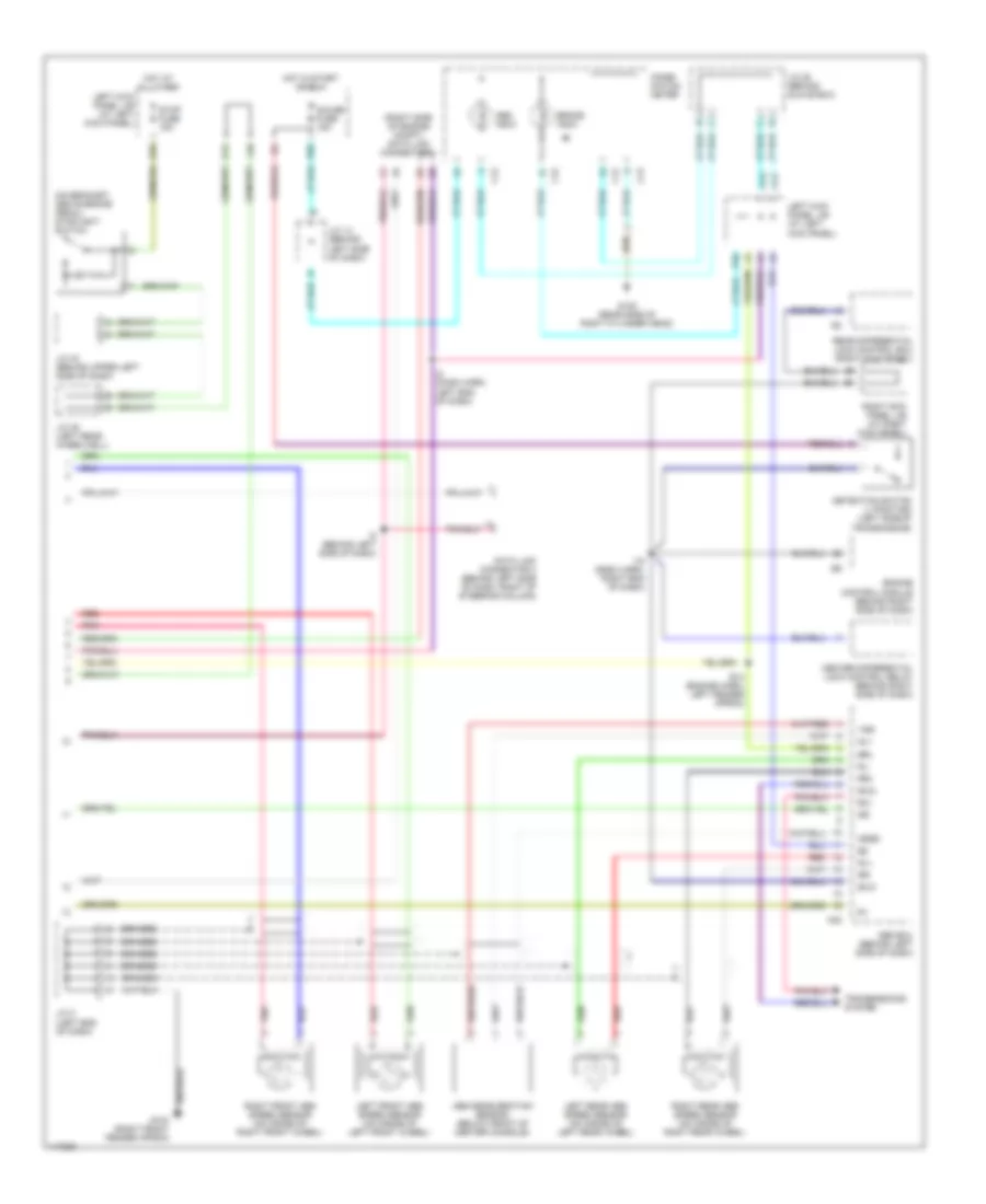
Anti-lock Brake Wiring Diagrams, without VSC (1 of 2) for Toyota Land Cruiser 2001
List of elements for Anti-lock Brake Wiring Diagrams, without VSC (1 of 2) for Toyota Land Cruiser 2001:
- (1998-99) (2000-01)
- A10
- A11
- A21
- A23
- Abs 1 fuse 40a 50a
- Abs 2 fuse 40a
- Abs actuator (on left rear corner of engine compt)
- Abs ecu (behind left side of dash)
- Abs mtr 1 relay
- Abs mtr 2 relay
- Abs sol relay
- B10
- B11
- B12
- B14
- Brake fluid level warning switch
- D/g
- D16
- E14
- Ecu-ig fuse 15a
- Engine controls system
- Engine room j/b (on left inner fender panel)
- Fl+
- Fl-
- Fr+
- Fr-
- G102
- G103 (right front fender apron)
- Grd1
- Grd2
- Grd3
- Grd4
- Hot at all times
- Hot in start or run
- I2 (dash harn, left end of dash)
- Ig1
- Ig2
- Ign fuse 10a
- J/c 2 (left end of dash)
- J/c 21 (behind glove box)
- Left kick panel j/b (at left kick panel)
- Mr1
- Mr2
- Mt+
- Mt-
- Pnk
- R1+
- R2+
- Red
- Sa1
- Sa2
- Sflh
- Sflr
- Sfrh
- Sfrr
- Srh
- Srr
- Stp
Anti-lock Brake Wiring Diagrams, without VSC (2 of 2) for Toyota Land Cruiser 2001
List of elements for Anti-lock Brake Wiring Diagrams, without VSC (2 of 2) for Toyota Land Cruiser 2001:
- (on bracket, above brake pedal) stoplight switch
- (right side of engine compt) data link connector 1
- A22
- Abs deceleration sensor (below front of center console)
- Abs ecu (behind left side of dash)
- Abs indic
- B10
- Braided
- Brake indic
- Brl
- C12
- C13
- C15
- Center differential lock control relay (behind right side of dash)
- Combi- nation meter
- Data link connector 3 (behind left side of dash, right of steering column)
- Detection switch (l position) (left side of transmission)
- E14 (engine harn, left fender apron)
- Engine control module (behind right side of dash)
- Exi
- Exi2
- Exi3
- G103 (right front fender apron)
- G120 (rear side of right cylinder head)
- Gauge fuse 15a
- Ggrd
- Gl1
- Hot at all times
- Hot in start or run
- I15 (dash harn, right end of dash)
- I2 (dash harn, left end of dash)
- I5 (behind left side of dash)
- J/c 14 (behind left side of dash)
- J/c 2 (left end of dash)
- J/c 28 (behind glove box)
- J/c 35 (left rear wheelwell)
- J/c 43 (behind upper left side of dash)
- J10
- Left front abs speed sensor (on inside of left front wheel)
- Left kick panel j/b (at left kick panel)
- Left rear abs speed sensor (on inside of left rear wheel)
- O12
- P10
- P11
- P12
- P83
- Pnk
- Rear differential lock control ecu (right kick panel)
- Red
- Right front abs speed sensor (on inside of right front wheel)
- Right kick panel j/b (at right kick panel)
- Right rear abs speed sensor (on inside of right rear wheel)
- Rl+
- Rl-
- Rr+
- Rr-
- Stop fuse 15a
- Transmssions system
- Vgs