ANTI-LOCK BRAKES
Anti-lock Brakes Wiring Diagram for Toyota Yaris S 2007
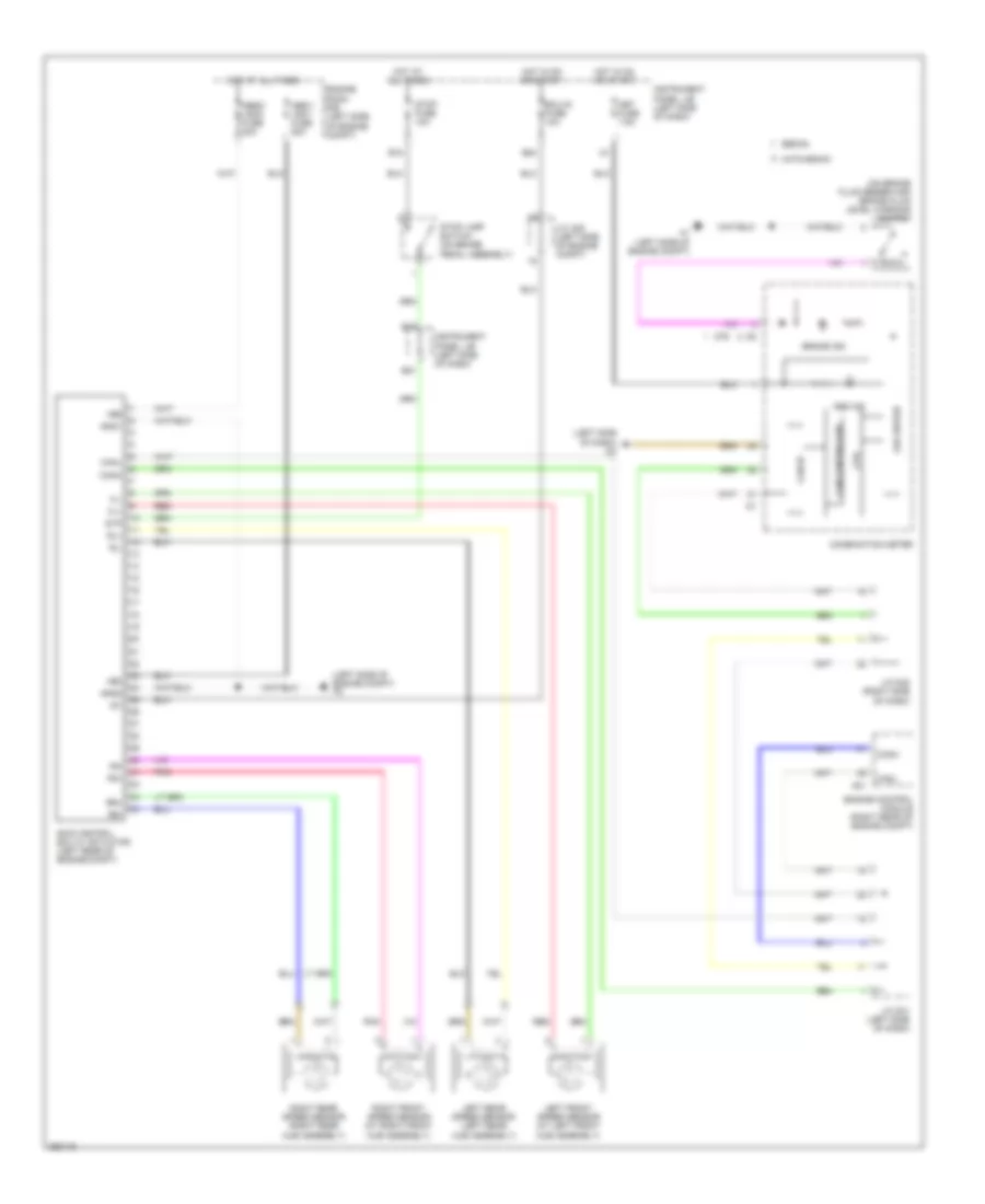
List of elements for Anti-lock Brakes Wiring Diagram for Toyota Yaris S 2007:
- (left side of dash) d3
- (left side of engine compt) a2
- (on brake fluid reservoir) brake fluid level warning switch
- +bm
- +bs
- A1 (left side of engine compt)
- A21
- Abs ind
- Abs1/ vsc1 fuse 50a
- Abs2/ vsc2 fuse 30a
- B12
- B18
- B21
- B24
- Brake ind
- Can controller
- Can i/f
- Canh
- Canl
- Combination meter
- Cpu
- D76
- Ecu-ig fuse 10a
- Engine control module (right rear of engine compt)
- Engine room r/b (left side of engine compt)
- Fl+
- Fl-
- Fr+
- Fr-
- Gnd1
- Gnd2
- Hatchback
- Hot at all times
- Hot in on or start
- Ig1
- Instrument panel j/b (left side of dash)
- J/c a25 (left side of engine compt)
- J/c d41 (left side of dash)
- J/c d42 (right side of dash)
- Led driver
- Left front speed sensor (at left front hub assembly)
- Left rear speed sensor (left rear hub assembly)
- Met fuse 7.5a
- Pnk
- Red
- Right front speed sensor (at right front hub assembly)
- Right rear speed sensor (right rear hub assembly)
- Rl+
- Rl-
- Rr+
- Rr-
- Sedan
- Skid control ecu w/ actuator (left rear of engine compt)
- Stop fuse 10a
- Stop lamp switch (on brake pedal assembly)
- Stp
 English