ANTI-THEFT
Anti-theft Wiring Diagram for Toyota MR2 1994
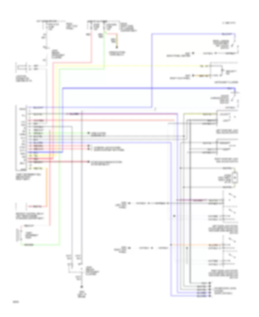
List of elements for Anti-theft Wiring Diagram for Toyota MR2 1994:
- 1995 vftc c
- Acc
- Ctsy
- Cty1
- D11
- Diode (for theft) (right side of i/p)
- Dome fuse 15a
- Fll
- Frl
- G200 (left kick panel)
- G200 (right kick panel)
- G202 (left i/p brace)
- G203 (right kick panel)
- G407 (back panel center)
- Haz-horn fuse 15a
- Horn
- Horn system (horn relay)
- Horns system (horn relay)
- Hot at all times
- Hot in run or acc
- Ind
- Instrument cluster
- Interior lights system (door courtesy switches)
- J/b #3 (behind instrument cluster)
- Junction connector (center of i/p)
- K/l
- K/lu
- Ksw
- Ksw2
- L/ul
- Left door key lock and unlock switch
- Left door lock motor, unlock detection switch and door open detection switch
- Lock
- Power door locks system (door lock ecu)
- R/b #1 (left kick panel)
- R/b #2 (right side of luggage compartment)
- Rad & cig fuse 15a
- Rear luggage compartment key unlock switch
- Red
- Retract control relay (left rear corner of engine compartment)
- Right door key lock and unlock switch
- Right door lock motor, unlock detection switch and door open detection switch
- Rtr
- Security ind
- Srly
- Starting/charging system (starter relay)
- Theft deterrent ecu (behind right front seat)
- Theft deterrent horn
- Unlock
- Unlock warning switch (ignition switch)
 English