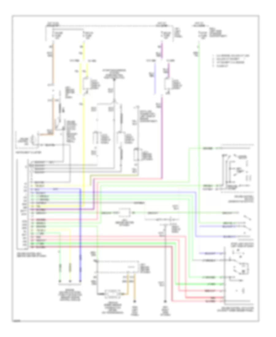
CRUISE CONTROL
Cruise Control Wiring Diagram for Toyota Tacoma SR5 1996
List of elements for Cruise Control Wiring Diagram for Toyota Tacoma SR5 1996:
- (a/t)
- (m/t)
- 3.4l engine, column a/t usa
- A/t except 2.4l engine
- A10
- Batt
- C10
- Cancel
- Ccs
- Cms
- Column a/t except
- Cruise control actuator (on right inner fender panel)
- Cruise control clutch switch (on bracket, above clutch pedal)
- Cruise control ecu (behind center of dash)
- Cruise control ind
- Cruise control switch (combination switch)
- D10
- D12
- D15
- D16
- D17
- Data link connector 1 (left side of engine compartment)
- Ect
- Ecu-b fuse 15a
- Ecu-ig fuse 15a
- Engine controls system (throttle position sensor, engine control module)
- Floor a/t
- G200 (left kick panel)
- G201 (right side of dash)
- Gauge fuse 10a
- Gnd
- Hot at all times
- Hot in on and start
- Idl
- Igb
- Instrument cluster
- J/b 1 (left kick panel)
- J/b 3 (behind center of dash)
- J/c 3 (behind center of dash)
- J/c 6 (right side of dash)
- J/c 8 (right side of dash)
- Main
- R/b 2 (left side of engine compartment)
- Red
- Resume/ accel
- Set/ coast
- Spd
- Starting/charging system (park/neutral position switch)
- Stop fuse 15a
- Stop light switch (left side of dash)
- Stp-
- Vehicle speed sensor (combination meter) (on transmission)
- Vr1
- Vr2
- Vr3
- W/ abs
- W/o abs
 English