CRUISE CONTROL
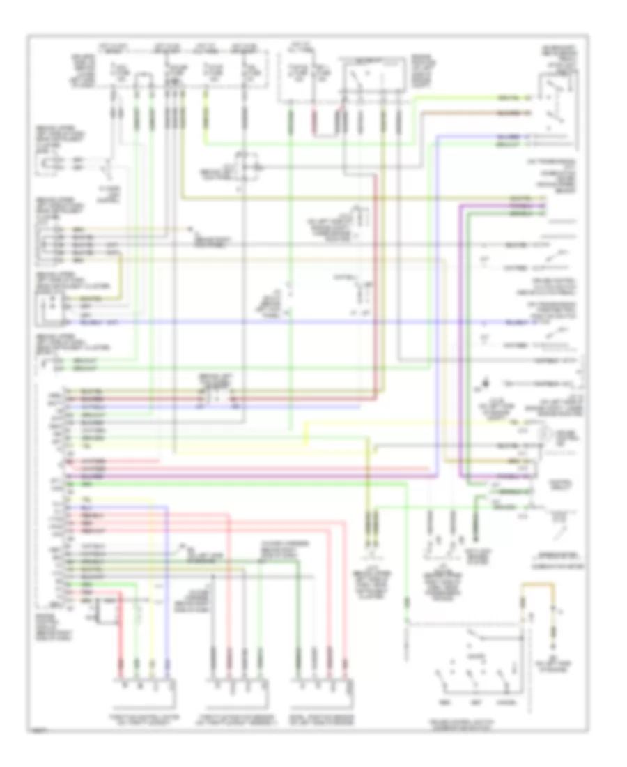
Cruise Control Wiring Diagram, Double Cab for Toyota Tundra Limited 2004

List of elements for Cruise Control Wiring Diagram, Double Cab for Toyota Tundra Limited 2004:
- (behind left side of dash) j/c 48
- (on bracket, above brake pedal) stoplight switch
- (on left side of engine compt)
- (on left side of firewall) ec
- +b2
- +bm
- +res
- -set
- Accelerator pedal position sensor (behind left side of dash, above accelerator pedal)
- Active circuit
- Anti-lock brakes system
- Batt
- C11
- C12
- C13
- C16
- Cancel
- Ccs
- Combination meter
- Control circuit
- Cruise control switch (combination switch)
- Cruise ind
- D position switch (park/neutral position switch) (on transmission)
- Driver's side j/b (under left end of dash)
- E01
- E02
- Eb (on right rear of engine)
- Ecc
- Efi 1 fuse 20a
- Efi relay
- Engine control module (behind right side of dash)
- Engine room j/b (on left side of engine compt)
- Epa
- Epa2
- Etcs fuse 10a
- Gauge fuse 15a
- Ge01
- Hot at all times
- Hot in on or start
- I1 (in dash harness, behind upper right end of dash)
- Ign 1 fuse 10a
- Igsw
- Ip (behind center of dash)
- Ipo
- J/c 28 & 29 (behind center of dash)
- J/c 34 (under engine room r/b)
- J/c 35
- J/c 45 (behind left side of dash)
- J/c 55 & 56 (behind right side of dash)
- J/c 55 (behind right side of dash)
- J28
- J29
- J55
- J56
- Mrel
- On/off
- Red
- S13
- S14
- Short connector (behind left side of dash)
- Spd
- Speedometer
- St1-
- Stop fuse 15a
- Stp
- Sub j/b 3 (behind center of dash)
- Throttle control motor & position sensor (on throttle body assembly)
- Vcp2
- Vcpa
- Vpa
- Vpa2
- Vta1
- Vta2
3.4L
3.4L, Cruise Control Wiring Diagram, Access/Standard Cab for Toyota Tundra Limited 2004
List of elements for 3.4L, Cruise Control Wiring Diagram, Access/Standard Cab for Toyota Tundra Limited 2004:
- (a/t)
- (behind left kick panel) j/c 26 & 27
- (behind upper left side of dash, near instrument cluster) diode (a/t)
- (behind upper left side of dash, near instrument cluster) j/c 10
- (behind upper left side of dash, near instrument cluster) j/c 8
- (behind upper left side of dash, near instrument cluster) j/c 9
- (in dash harness, behind right side of dash) i3
- (m/t)
- (on bracket, above brake pedal) stoplight switch
- (on transmission) (m/t) (combination meter) vehicle speed sensor
- (on transmission) park/neutral position switch
- +bm
- -set
- A/t
- Acc fuse 15a
- Accel position sensor (on left side of engine)
- Anti-lock brakes system
- Batt
- C11
- C12
- C13
- C16
- Cancel
- Ccs
- Cl+
- Cl-
- Combination meter
- Control circuit
- Cruise control clutch switch (above clutch pedal)
- Cruise control ind
- Cruise control switch (combination switch)
- Driver's side j/b (behind lower left side of dash)
- E04
- Ed (on left side of engine)
- Efi 1 fuse 15a
- Efi relay
- Engine control module (behind right side of dash)
- Engine room r/b (on left side of engine compt)
- Etcs fuse 15a
- F11
- G11
- Gauge fuse 10a
- Ge01
- Hot at all times
- Hot in acc or on
- Hot in on or start
- I3 (in dash harness, behind right side of dash)
- Ign fuse 5a
- Igsw
- Ih (behind right kick panel)
- J/c 18 (on left side of engine compt, under engine room r/b)
- J/c 2 (on left side of engine compt, under engine room r/b)
- J/c 25 (on left side of engine compt)
- J/c 26 & 27 (behind left kick panel)
- J/c 28 & 29 (behind upper right side of dash, near passenger's air bag)
- J/c 4 (behind left kick panel)
- J/c 9 (behind upper left side of dash, near instrument cluster)
- J26
- J27
- J28
- J29
- M/t
- Me01
- Mrel
- Nca
- On/off
- Red
- Res
- Sp1
- Speedometer
- St1-
- Stop fuse 15a
- Stp
- Throttle control motor (on throttle body)
- Throttle position sensor (on throttle body assembly)
- Vpa
- Vpa2
- Vta
- Vta2
- W/ door lock control
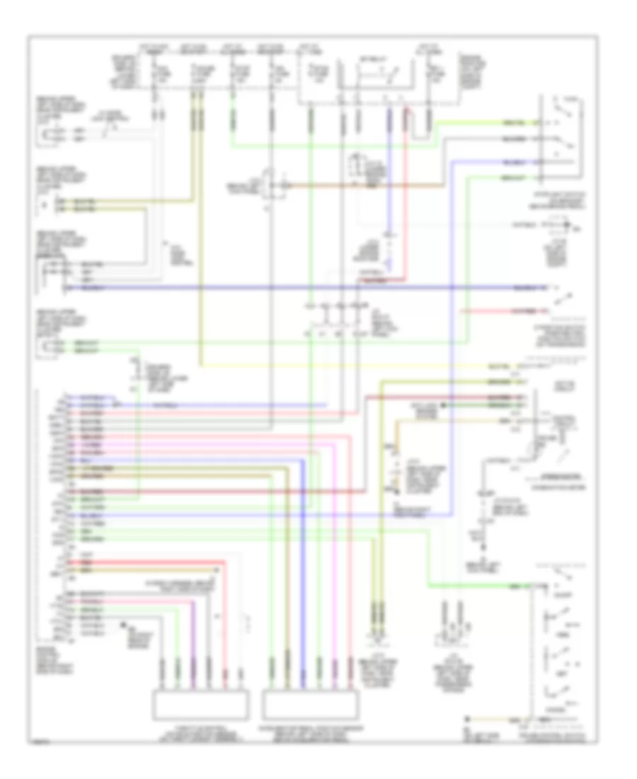
4.7L
4.7L, Cruise Control Wiring Diagram, Access/Standard Cab for Toyota Tundra Limited 2004
List of elements for 4.7L, Cruise Control Wiring Diagram, Access/Standard Cab for Toyota Tundra Limited 2004:
- (behind left end of dash)
- (behind upper left side of dash, near instrument cluster)
- (behind upper left side of dash, near instrument cluster) diode (a/t)
- (behind upper left side of dash, near instrument cluster) j/c 10
- (behind upper left side of dash, near instrument cluster) j/c 8
- (behind upper left side of dash, near instrument cluster) j/c 9
- (on left side of engine compt)
- +b2
- +bm
- +res
- -set
- Acc fuse 15a
- Accelerator pedal position sensor (behind left side of dash, above accelerator pedal)
- Active circuit
- Anti-lock brakes system
- Batt
- C11
- C12
- C13
- C16
- Cancel
- Ccs
- Combination meter
- Control circuit
- Cruise control switch (combination switch)
- Cruise ind
- D position switch (park/neutral position switch) (on transmission)
- Driver's side j/b (behind lower left side of dash)
- E01
- E02
- Eb (on right rear of engine)
- Ec (on left side of firewall)
- Ecc
- Efi 1 fuse 15a
- Efi relay
- Engine control module (behind right side of dash)
- Engine room r/b (on left side of engine compt)
- Epa
- Epa2
- Etcs fuse 10a
- F11
- G11
- Gauge fuse 10a
- Ge01
- Hot at all times
- Hot in acc or on
- Hot in on or start
- I3 (in dash harness, behind right side of dash)
- Ie (behind left kick panel)
- Ign fuse 5a
- Igsw
- Ih (behind right kick panel)
- J/c 18 (under engine room r/b)
- J/c 2 (under engine room r/b)
- J/c 23 & 24
- J/c 25
- J/c 26 & 27 (behind left kick j27 panel)
- J/c 28 & 29 (behind upper left side of dash, near passenger's air bag)
- J/c 4 (behind left kick panel)
- J/c 8
- J/c 9 (behind upper left side of dash, near instrument cluster)
- J23
- J24
- J26
- J28
- J29
- Mrel
- On/off
- Red
- Spd
- Speedometer
- St1-
- Stop fuse 15a
- Stoplight switch (on bracket, above brake pedal)
- Stp
- Throttle control motor & position sensor (on throttle body assembly)
- Vcp2
- Vcpa
- Vpa
- Vpa2
- Vta1
- Vta2
- W/ door lock control
- W/o door lock control