ENGINE PERFORMANCE
2.7L
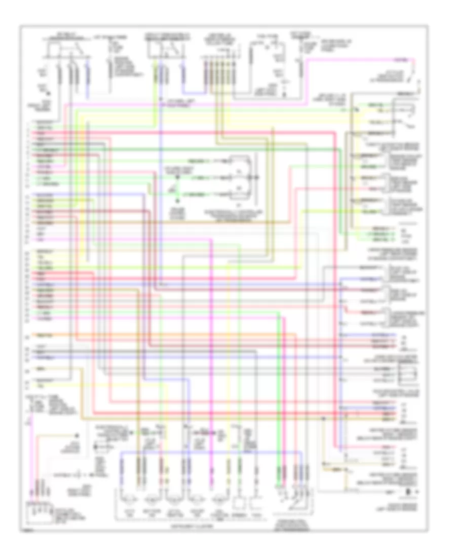
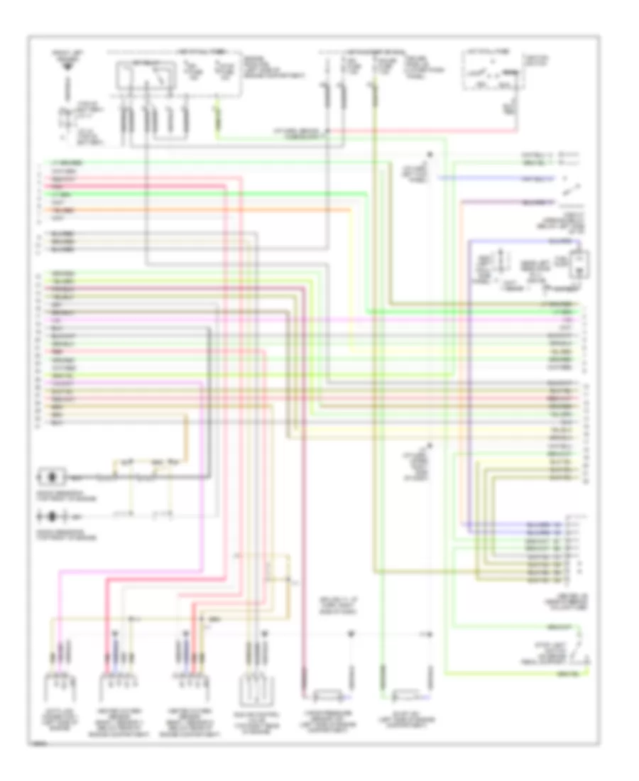
2.7L, Engine Performance Wiring Diagrams, A/T (1 of 2) for Toyota 4Runner 1996

List of elements for 2.7L, Engine Performance Wiring Diagrams, A/T (1 of 2) for Toyota 4Runner 1996:
- #10
- #20
- (eng harn, top left of engine)
- (i/p harn, behind fuse box)
- (near steering column) center j/b
- (splice i11: i/p harn right side of dash)
- 4wd
- A/c system
- Ac1
- Acc
- Act
- Add ind switch (4wd only)
- Batt
- Conn e6
- Conn e7
- Conn e8
- Conn e9
- Crankshaft position sensor (left side of engine)
- Cruise control system
- Data link connector 1 (left side of engine)
- Distributor (right front of engine)
- Driver side j/b (lower finish panel)
- E01
- E02
- E03
- Egr
- Engine control module (right side of i/p, behind glove box)
- Engine room r/b (left side of engine compartment)
- Evp
- Ext
- G131 (intake manifold)
- Hot at all times
- Hot at all times ignition switch
- Ht1
- Ht2
- I11
- Idl
- Ig-
- Igf
- Igf1
- Ign fuse 7.5a
- Igniter (right side of engine compartment)
- Igt
- Injector #1
- Injector #2
- Injector #3
- Injector #4
- Knk
- Lock
- Ne-
- Noise filter (right side of engine compt)
- Od1
- Od2
- Oil
- Oil-w
- Ox1
- Ox2
- Pnk
- Ptnk
- Pwr
- Red
- Rsc
- Rso
- Run
- Sdl
- Sp1
- Sp2+
- Sp2-
- Sta
- Start
- Start/ charge system
- Stop fuse 10a
- Stop light switch (on brake pedal support)
- Te1
- Tfn
- Tha
- Thg
- Thw
- Tpc
- Vcc
- Vehicle speed sensor (electronically controlled transmission)
- Vta
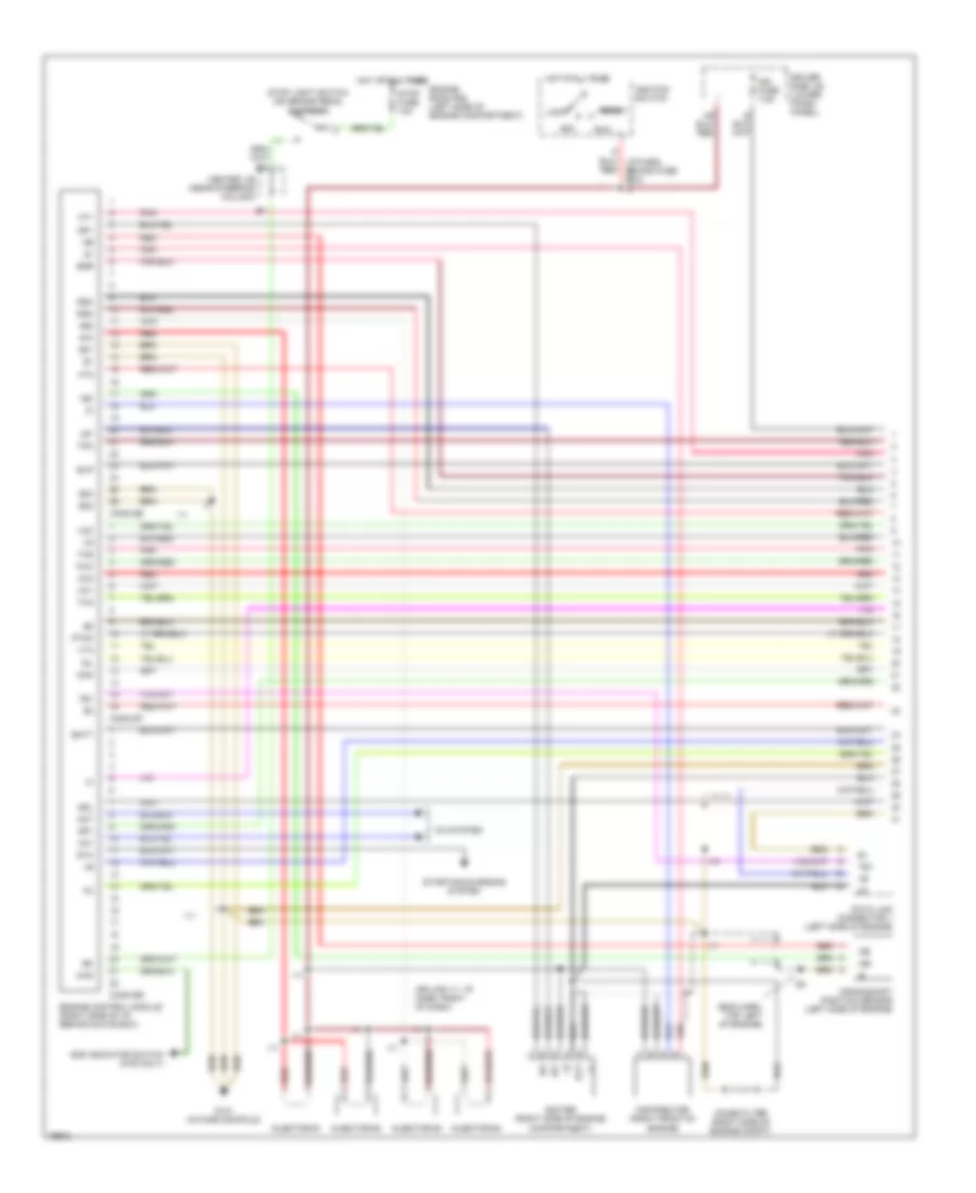
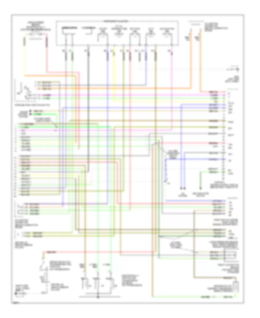
2.7L, Engine Performance Wiring Diagrams, A/T (2 of 2) for Toyota 4Runner 1996
List of elements for 2.7L, Engine Performance Wiring Diagrams, A/T (2 of 2) for Toyota 4Runner 1996:
- (i/p harn, left kick panel)
- (i/p harn, right side of dash) i11
- (splice i11: i/p harn, right side
- A/t fluid temp switch (in transmission)
- A/t oil temp ind
- A/t p ind
- B11
- Bat
- C11
- C12
- C14
- Cen- ter j/b (near steer col)
- Center j/b (near steering column tube)
- Circuit opening relay (below left side of i/p)
- Cruise control system
- Data link connector 3 (below center of i/p)
- Driver side j/b (lower finish panel)
- Ect pwr ind
- Efi fuse 15a
- Efi relay (engine room r/b)
- Egr gas temp sensor (left side of engine)
- Egr vsv (left side of engine)
- Electronically controlled trans pattern select sw
- Electronically controlled transmission solenoid (on transmission)
- Engine coolant temp sensor (top rear of engine)
- Engine room r/b (left side of engine compartment)
- Engine room r/b (left side of engine compt)
- Evap vsv (left side of engine compartment)
- Fuel pump
- G100 (front left fender)
- G131 (intake manifold)
- G200 (left cowl side panel)
- G202 (left cowl side panel)
- G203 (right cowl side panel)
- Gauge fuse 10a
- Heated oxygen sensor (bank 1 sensor 1) (below rear of engine compt)
- Heated oxygen sensor (bank 1 sensor 2) (below rear of engine compt)
- Hot at all times
- Hot in run or start
- I11
- Idle air control valve (left side of engine)
- Instrument cluster
- Intake air temp sensor (on air cleaner assembly)
- J/c j6 (left dash)
- Knock sensor (left side of engine)
- Mal- function ind
- Mass air flow meter (on air cleaner assembly)
- O/d main sw
- O/d off ind
- Obd fuse 7.5a
- Of dash)
- Park/neutral position switch (on transmission)
- Pnk
- Ptnk
- Red
- Sdl
- Speedo
- Tach
- Throttle position sensor (left side of engine)
- Vapor pressure sensor (left rear corner of engine compartment)
- Vapor pressure sensor vsv (left side of engine compt)
- Vcc
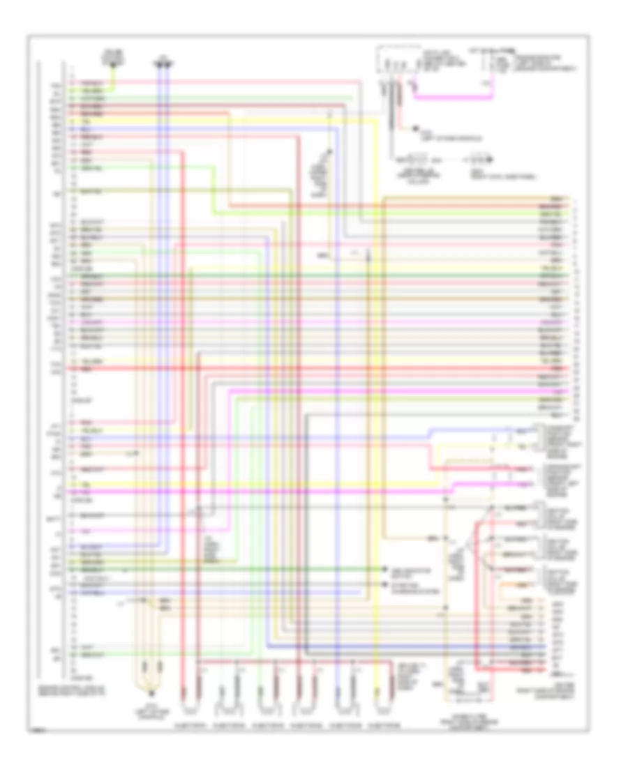
2.7L, Engine Performance Wiring Diagrams, M/T (1 of 2) for Toyota 4Runner 1996
List of elements for 2.7L, Engine Performance Wiring Diagrams, M/T (1 of 2) for Toyota 4Runner 1996:
- #10
- #20
- (eng harn, top left of engine)
- (splice i11: i/p harn, right of dash)
- 4wd
- A/c system
- Ac1
- Acc
- Act
- Add indicator switch (4wd only)
- Batt
- Center j/b (near steering column)
- Conn e6
- Conn e7
- Conn e9
- Crankshaft position sensor (left side of engine)
- Data link connector 1 (left side of engine)
- Distributor (right front of engine)
- Driver side j/b (lower finish panel)
- E01
- E02
- E03
- Egr
- Engine control module (right side of i/p, behind glove box)
- Engine room r/b (left side of engine compartment)
- Evp
- Ext
- G131 (intake manifold)
- Hot at all times
- Ht1
- Ht2
- I10
- I11
- Idl
- Ig-
- Igf
- Igf1
- Ign fuse 7.5a
- Igniter (right side of engine compartment)
- Ignition switch
- Igt
- Injector #1
- Injector #2
- Injector #3
- Injector #4
- Knk
- Lock
- Ne-
- Noise filter (right side of engine compt)
- Ox1
- Ox2
- Pnk
- Ptnk
- Red
- Rsc
- Rso
- Run
- Sdl
- Sp1
- Sta
- Start
- Starting/charging system
- Stop fuse 10a
- Stop light switch (on brake pedal support)
- Te1
- Tha
- Thg
- Thw
- Tpc
- Vcc
- Vta
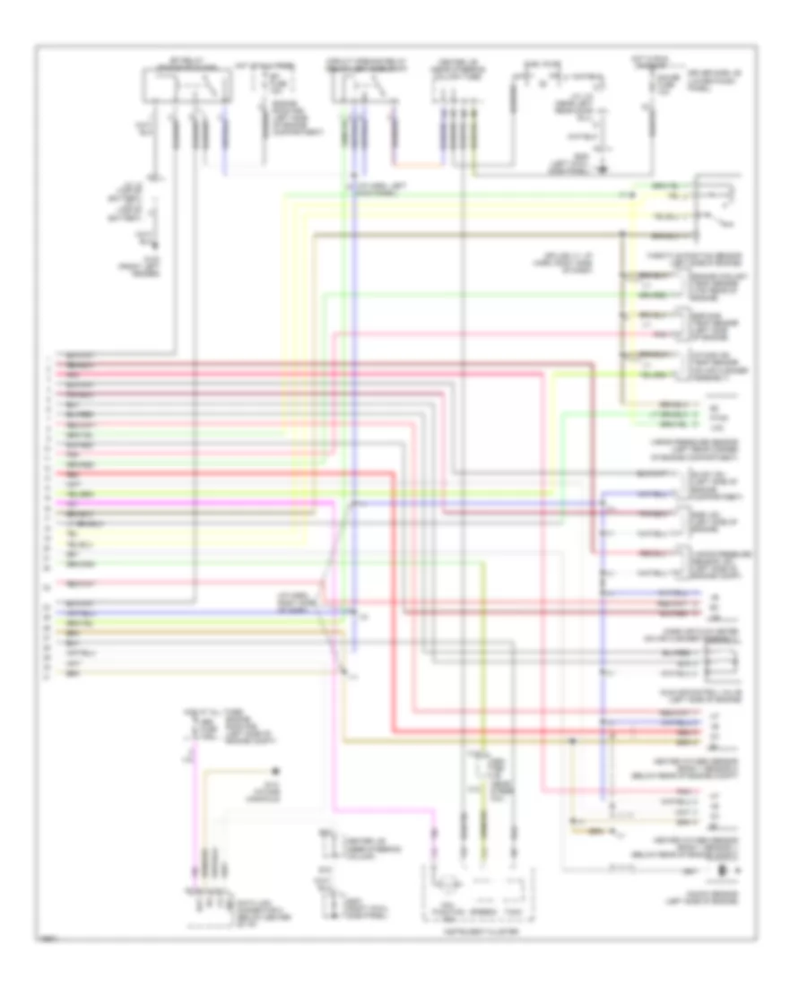
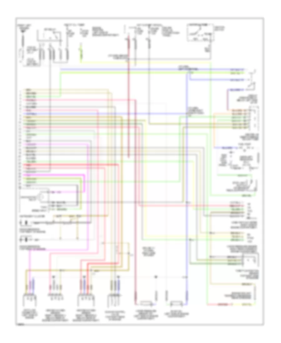
2.7L, Engine Performance Wiring Diagrams, M/T (2 of 2) for Toyota 4Runner 1996
List of elements for 2.7L, Engine Performance Wiring Diagrams, M/T (2 of 2) for Toyota 4Runner 1996:
- (i/p harn, left kick panel)
- (i/p harn, right side of dash)
- (splice i11: i/p harn, right side of dash)
- Bat
- C12
- C14
- Cen- ter j/b (near steer col)
- Center j/b (near steering column tube)
- Center j/b (neer steering column)
- Circuit opening relay (below left side of i/p)
- Data link connector 3 (below center of i/p)
- Driver side j/b (lower finish panel)
- E15
- E22
- Efi fuse 15a
- Efi relay (engine room r/b)
- Egr gas temp sensor (left side of engine)
- Egr vsv (left side of engine)
- Engine coolant temp sensor (top rear of engine)
- Engine room r/b (left side of engine compartment)
- Engine room r/b (left side of engine compt)
- Evap vsv (left side of engine compartment)
- Fuel pump
- G100 (front left fender)
- G131 (intake manifold)
- G200 (left cowl side panel)
- G203 (right cowl side panel)
- Gauge fuse 10a
- Heated oxygen sensor (bank 1 sensor 1) (below rear of engine compt)
- Heated oxygen sensor (bank 1 sensor 2) (below rear of engine compt)
- Hot at all times
- Hot in run or start
- I10
- I11
- Idle air control valve (left side of engine)
- Instrument cluster
- Intake air temp sensor (on air cleaner assembly)
- J/c j12 (near left rear door sill)
- J/c j2 (top of battery) j/c j1 (top of battery)
- Knock sensor (left side of engine)
- Mal- function ind
- Mass air flow meter (on air cleaner assembly)
- Obd fuse 7.5a
- Pnk
- Ptnk
- Red
- Sdl
- Speedo
- Tach
- Throttle position sensor (left side of engine)
- Vapor pressure sensor (left rear corner of engine compartment)
- Vapor pressure sensor vsv (left side of engine compt)
- Vcc
3.4L
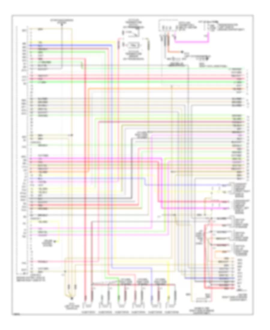
3.4L, Engine Performance Wiring Diagrams, A/T (1 of 3) for Toyota 4Runner 1996
List of elements for 3.4L, Engine Performance Wiring Diagrams, A/T (1 of 3) for Toyota 4Runner 1996:
- #10
- #20
- #30
- #40
- #50
- #60
- (i/p harn, right side of
- (i/p harn, right side of dash)
- A/t fluid temperature sensor (on transmission)
- A/t fluid temperature switch (on transmission)
- Camshaft position sensor (front right side of engine)
- Center j/b (near str col)
- Conn e10
- Conn e11
- Conn e12
- Crankshaft position sensor (front left side of engine)
- Cruise control system
- Dash)
- Data link connector 3 (below center of i/p)
- E02
- E03
- E15
- E22
- Engine control module (behind right side of i/p)
- Engine room r/b (left side of engine compartment)
- Evp
- Ext
- F13
- G131 (left intake manifold)
- G203 (right cowl side panel)
- Gnd
- Hot at all times
- Ht1
- Ht2
- I11
- Idl
- Igc1
- Igc2
- Igc3
- Igf
- Igniter (right side of engine compartment)
- Ignition coil #1 (right side of engine)
- Ignition coil #2 (right side of engine)
- Ignition coil #3 (right side of engine)
- Igt1
- Igt2
- Igt3
- Injector #1
- Injector #2
- Injector #3
- Injector #4
- Injector #5
- Injector #6
- Knk1
- Knk2
- Ne-
- Noise filter (right side of engine compartment)
- Obd fuse 7.5a
- Oil
- Ox1
- Ox2
- Pnk
- Ptnk
- Red
- Rsc
- Rso
- Sdl
- Sp2-
- Sta
- Starting/charging system
- Te1
- Tha
- Thw
- Tpc
- Vcc
- Vta
3.4L, Engine Performance Wiring Diagrams, A/T (2 of 3) for Toyota 4Runner 1996
List of elements for 3.4L, Engine Performance Wiring Diagrams, A/T (2 of 3) for Toyota 4Runner 1996:
- (front left fender) g100
- (i/p harn, behind fuse block)
- (near left rear door sill) j/c j12
- (splice i11: i/p harn, right side of dash)
- (top of battery) j/c j1
- Acc
- Center j/b (near steering column tube)
- Circuit opening relay (below left side of i/p)
- Data link connector 1 (left side of engine)
- Driver side j/b (lower finish panel)
- Efi fuse 15a
- Efi relay
- Engine room r/b (left side of engine compartment)
- Evap vsv (left side of engine compartment)
- Fuel pump
- G200 (left cowl side panel)
- Gauge fuse 7.5a
- Heated oxygen sensor (bank 1 sensor 1) (below rear of engine compartment)
- Heated oxygen sensor (bank 1 sensor 2) (below rear of engine compartment)
- Hot at all times
- Hot in start or run
- I10 (i/p harn, upper right side of dash)
- I11
- I2 (i/p harn, left kick panel)
- Idle air control valve (top right rear of engine)
- Ign fuse 7.5a
- Ignition switch
- J/c j2 (top of battery)
- Knock sensor #1 (top front of engine)
- Knock sensor #2 (top front of engine)
- Lock
- Pnk
- Red
- Run
- Start
- Stop fuse 10a
- Stop light switch (on brake pedal support)
- Te1
- Vapor pressure sensor vsv (left side of engine compartment)
3.4L, Engine Performance Wiring Diagrams, A/T (3 of 3) for Toyota 4Runner 1996
List of elements for 3.4L, Engine Performance Wiring Diagrams, A/T (3 of 3) for Toyota 4Runner 1996:
- (i/p harn, right side of dash)
- (i/p harn, upper right side of dash)
- (right side cowl panel) g203
- 4wd
- A/c system
- A/t oil temperature ind
- A/t p ind
- Ac1
- Act
- Add indicator switch
- Batt
- C12
- C14
- Center j/b (near steering column)
- Conn e13
- Cruise control system
- Detection switch (transfer neutral position) (on transmission)
- E15
- Ect pwr ind
- Electroniclly controlled transmission solenoid (on transmission)
- Engine control module (behind right side of i/p)
- Engine coolant temperature sensor (rear of engine)
- G200 (left side cowl panel)
- I10
- I11
- Instrument cluster
- J5 junction connector (behind combination meter)
- J6 junction connector (behind combination meter)
- Malfunction ind
- Mass air flow meter (right side of engine compartment)
- O/d off ind
- Od1
- Od2
- Oil-w
- Park/neutral position switch
- Ptnk
- Pwr
- Sdl
- Sp1
- Speedometer
- Tachometer
- Tfn
- Tha
- Throttle position sensor (top right side of engine)
- Vapor pressure sensor (right rear corner of engine compartment)
- Vcc
- Vehicle speed sensor (electronically controlled transmission)
3.4L, Engine Performance Wiring Diagrams, M/T (1 of 2) for Toyota 4Runner 1996
List of elements for 3.4L, Engine Performance Wiring Diagrams, M/T (1 of 2) for Toyota 4Runner 1996:
- #10
- #20
- #30
- #40
- #50
- #60
- (i/p harn, right side dash)
- (i/p harn, right side of dash)
- (splice i11: i/p harn, right side of dash)
- 4wd
- 4wd only
- A/c system
- Ac1
- Act
- Add indicator switch
- Batt
- Camshaft position sensor (front right side of engine)
- Center j/b (near steering
- Column)
- Conn e6
- Conn e7
- Conn e8
- Conn e9
- Crankshaft position sensor (front left side of engine)
- Cruise control system
- Data link connector 3 (below center of i/p)
- E01
- E02
- E03
- E15
- E22
- Engine control module (behind right side of i/p)
- Engine room r/b (left side of engine compartment)
- Evp
- Ext
- G131 (left intake manifold)
- G203 (right cowl side panel)
- Gnd
- Hot at all times
- Ht1
- Ht2
- I10 (i/p harn, upper right side of dash)
- I11
- Idl
- Igc1
- Igc2
- Igc3
- Igf
- Igniter (right side of engine compartment)
- Ignition coil #1 (right side of engine)
- Ignition coil #2 (right side of engine)
- Ignition coil #3 (right side of engine)
- Igt1
- Igt2
- Igt3
- Injector #1
- Injector #2
- Injector #3
- Injector #4
- Injector #5
- Injector #6
- Knk1
- Knk2
- Ne-
- Noise filter (right side of engine compartment)
- Obd fuse 7.5a
- Ox1
- Ox2
- Pnk
- Ptnk
- Red
- Rsc
- Rso
- Sdl
- Sp1
- Sta
- Starting/ charging system
- Te1
- Tha
- Thw
- Tpc
- Vcc
- Vta
3.4L, Engine Performance Wiring Diagrams, M/T (2 of 2) for Toyota 4Runner 1996
List of elements for 3.4L, Engine Performance Wiring Diagrams, M/T (2 of 2) for Toyota 4Runner 1996:
- (front left fender) g100
- (i/p harn, behind fuse block) i3
- (i/p harn, left kick panel)
- (i/p harn, upper right side of dash) i10
- (near left rear door sill) j/c j12
- (splice i11: i/p harn, right side of dash)
- (top of battery j/c j1
- Acc
- Center j/b (near steering column tube)
- Circuit opening relay (below left side of i/p)
- Data link connector 1 (left side of engine)
- Driver side j/b (lower finish panel)
- Efi fuse 15a
- Efi relay
- Engine coolant temperature sensor (rear of engine)
- Engine room r/b (left side of engine compartment)
- Evap vsv (left side of engine compartment)
- Fuel pump
- G200 (left cowl side panel)
- Gauge fuse 7.5a
- Heated oxygen sensor (bank 1 sensor 1) (below rear of engine compartment)
- Heated oxygen sensor (bank 1 sensor 2) (below rear of engine compartment)
- Hot at all times
- Hot in start or run
- I11
- Idle air control valve (top right rear of engine)
- Ign fuse 7.5a
- Ignition switch
- Instrument cluster
- J/c j2 (top of battery)
- Knock sensor #1 (top front of engine)
- Knock sensor #2 (top front of engine)
- Lock
- Malfunction ind lp
- Mass air flow meter (right side of engine compartment)
- Pnk
- Ptnk
- Red
- Run
- Speed input
- Start
- Stop fuse 10a
- Stop light switch (on brake pedal support)
- Tach
- Te1
- Tha
- Throttle position sensor (top right side of engine)
- Vapor pressure sensor (right rear corner of engine compartment)
- Vapor pressure sensor vsv (left side of engine compartment)
- Vcc