ENGINE PERFORMANCE
2.2L
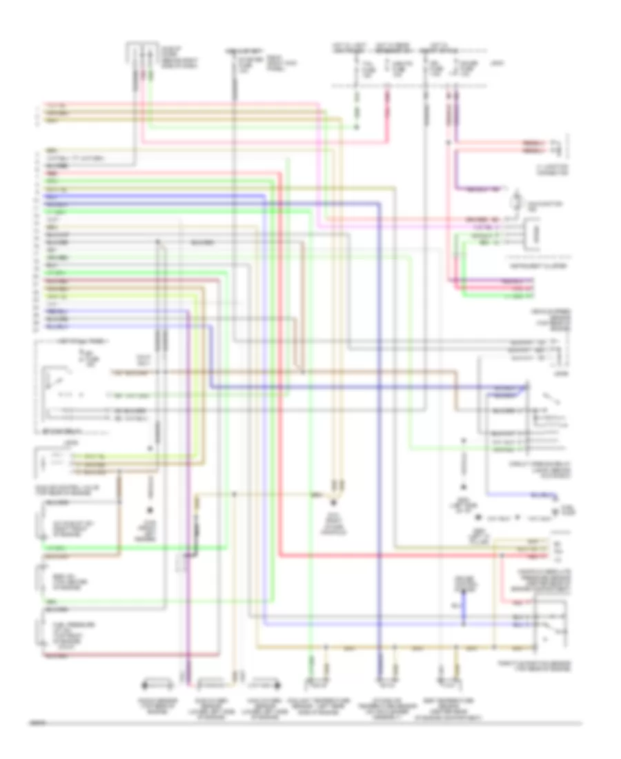
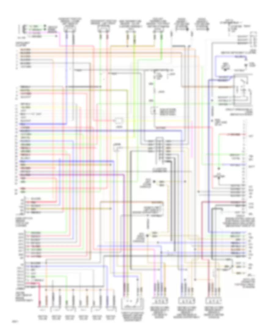
2.2L, Engine Performance Wiring Diagrams, A/T & California M/T (1 of 2) for Toyota Camry SE 1994

List of elements for 2.2L, Engine Performance Wiring Diagrams, A/T & California M/T (1 of 2) for Toyota Camry SE 1994:
- #10
- #20
- #30
- #40
- +b1
- A/c amplifier
- Aca
- Acc
- Act
- Batt
- Calif
- Canada
- Coil-
- Conn a
- Conn b
- Conn c
- Data link connector 1 (right rear corner of engine compartment)
- Data link connector 2 (behind left side of dash)
- Distributor
- E01
- E02
- Egr
- Els
- Eng
- Engine control module (ecm) (behind right side of dash)
- Ex calif m/t
- Ex canada
- Fed
- Fpu
- G1 (calif) g+ (fed)
- G131 (left intake manifold)
- G2 (calif) ne- (fed)
- Hot at all times
- Idl
- Ig-
- Igf
- Igniter (left side of engine compartment)
- Ignition coil (part of distributor assembly) (calif)
- Ignition switch
- Igt
- Injector #1
- Injector #2
- Injector #3
- Injector #4
- Iscc
- Isco
- Iscv
- J/b #1
- J/b #3
- Knk
- Lock
- Nca
- Ne (calif) ne+ (fed)
- Neutral start switch
- Noise filter (left side of engine compartment)
- Nsw
- Ox1
- Ox2
- Pim
- Red
- Run
- Sp1
- Sta
- Start
- Tachometer
- Te1
- Te2
- Tha
- Thg
- Thw
- Vf1
- Vta
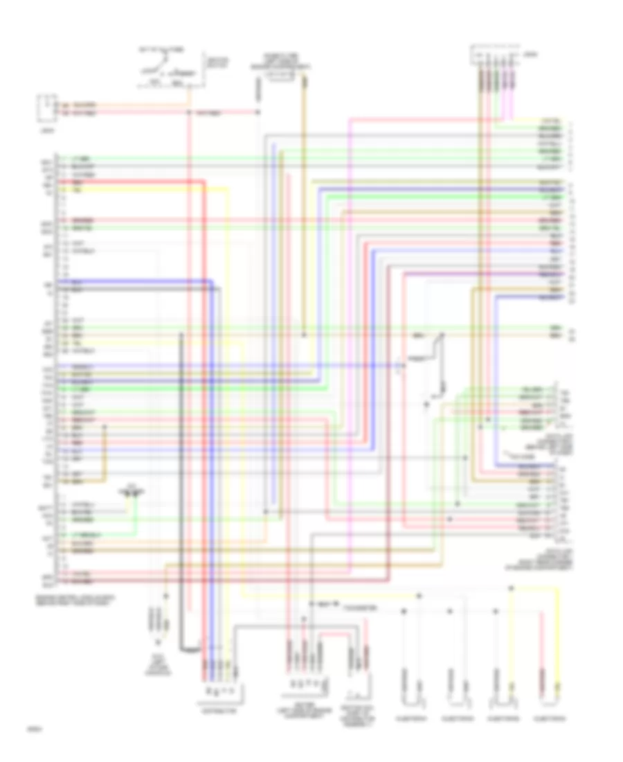
2.2L, Engine Performance Wiring Diagrams, A/T & California M/T (2 of 2) for Toyota Camry SE 1994
List of elements for 2.2L, Engine Performance Wiring Diagrams, A/T & California M/T (2 of 2) for Toyota Camry SE 1994:
- (calif)
- (left rear
- A/c idle-up vsv (right front of engine)
- A10
- B20
- Calif only
- Circuit opening relay (j/b #3) (behind glove box)
- Coolant temperature
- Cruise control system
- D14
- Efi fuse 15a
- Efi main relay
- Egr temperature sensor (center rear of engine compartment)
- Egr vsv (top center of engine)
- Fuel pressure up vsv (top front of engine)
- Fuel pump
- G100 (front left fender)
- G131 (right intake manifold)
- G202 (left side of i/p)
- G900 (left "a" pillar)
- Gauge fuse 10a
- Hot at all times
- Hot in start
- Hot in start or run
- Hot w/ light switch on
- Hot w/ rear defogger on
- Idle air control valve (top rear of engine)
- Idle-up diode (behind right side of dash)
- Ign fuse 7.5a
- Instrument cluster
- Intake air temperature sensor (on air cleaner assembly)
- J/b #1
- J/b #2
- J/b #6
- J1 junction connector
- Knock sensor (top rear of engine)
- Main oxygen sensor (lower left side of engine)
- Malfunction ind
- Manifold absolute pressure sensor (center rear of engine compartment)
- Mir-htr fuse 10a
- Nca
- Pim
- Pnk
- R/b #1 (right kick panel)
- Red
- Sensor
- Side of engine)
- Speed
- Starter fuse 10a
- Sub oxygen sensor (lower left side of engine)
- Tail fuse 15a
- Throttle position sensor (top rear of engine)
- Vehicle speed sensor (top rear of engine)
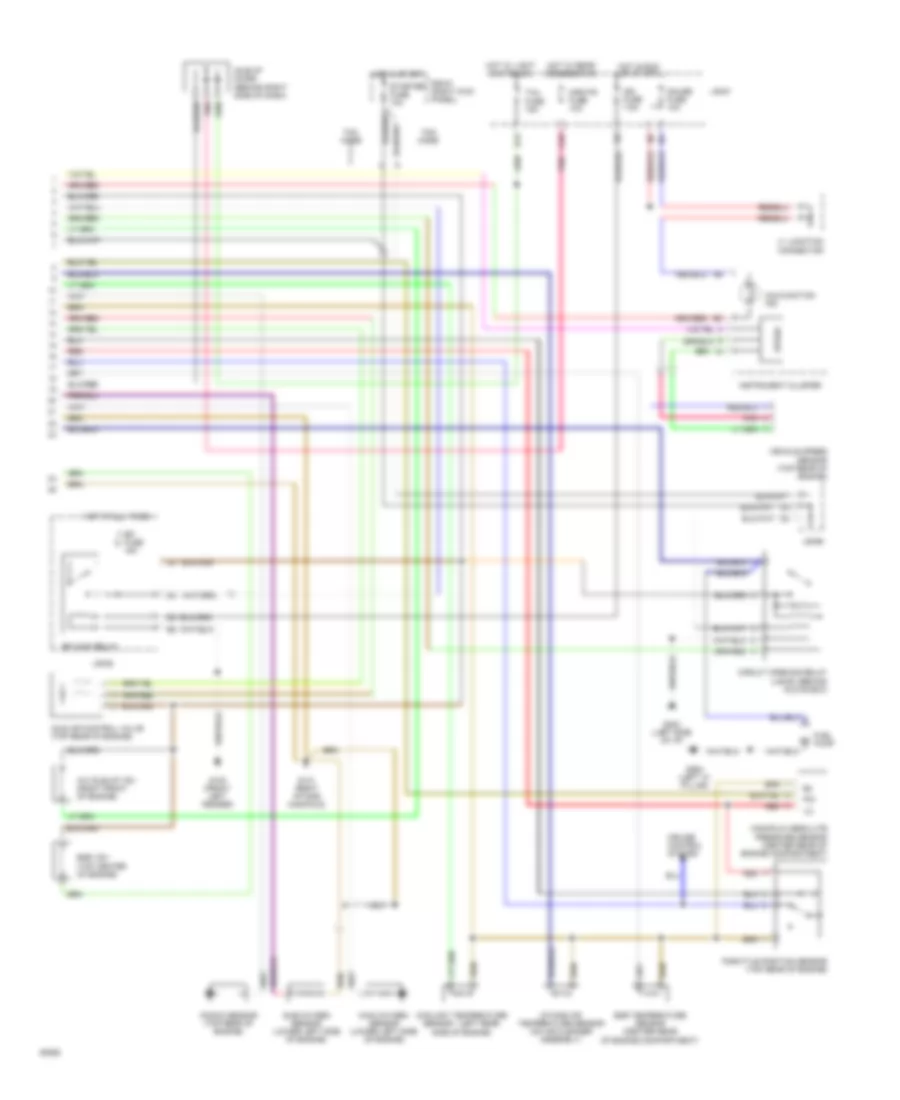
2.2L, Engine Performance Wiring Diagrams, M/T Except California (1 of 2) for Toyota Camry SE 1994
List of elements for 2.2L, Engine Performance Wiring Diagrams, M/T Except California (1 of 2) for Toyota Camry SE 1994:
- #10
- #20
- A/c amplifier
- Aca
- Acc
- Act
- Batt
- Coil-
- Data link connector 1 (right rear corner of engine compartment)
- Data link connector 2 (behind left side of dash)
- Distributor
- E01
- E02
- E21
- Egr
- Els
- Eng
- Engine control module (ecm) (behind right side of dash)
- G131 (left intake manifold)
- Hot at all times
- Idl
- Ig-
- Igf
- Igniter (left side of engine compartment)
- Ignition coil (part of distributor assembly)
- Ignition switch
- Igt
- Injector #1
- Injector #2
- Injector #3
- Injector #4
- Iscc
- Isco
- Iscv
- J/b #1
- J/b #3
- Knk
- Lock
- Nca
- Ne+
- Ne-
- Noise filter (left side of engine compartment)
- Ox1
- Ox2
- Pim
- Red
- Run
- Spd
- Sta
- Start
- Tachometer
- Te1
- Te2
- Tha
- Thg
- Thw
- Tmc made
- Vf1
- Vta
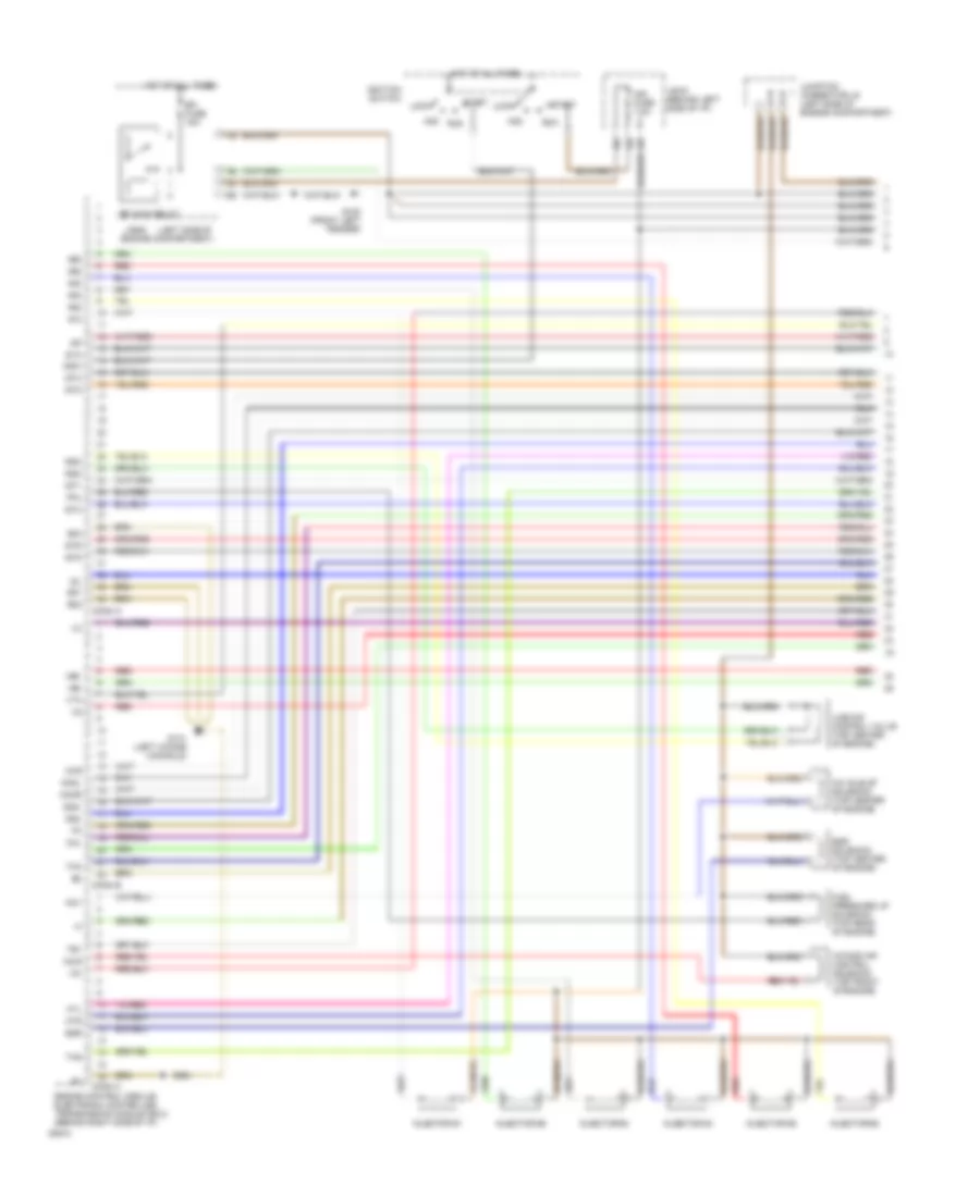
2.2L, Engine Performance Wiring Diagrams, M/T Except California (2 of 2) for Toyota Camry SE 1994
List of elements for 2.2L, Engine Performance Wiring Diagrams, M/T Except California (2 of 2) for Toyota Camry SE 1994:
- (left rear
- A/c idle-up vsv (right front of engine)
- A10
- Circuit opening relay (j/b #3) (behind glove box)
- Coolant temperature
- Cruise control system
- D14
- Efi fuse 15a
- Efi main relay
- Egr temperature sensor (center rear of engine compartment)
- Egr vsv (top center of engine)
- Fuel pump
- G100 (front left fender)
- G131 (right intake manifold)
- G202 (left side of i/p)
- G900 (left "a" pillar)
- Gauge fuse 10a
- Hot at all times
- Hot in run or start
- Hot in start
- Hot w/ light switch on
- Hot w/ rear defogger on
- Idle air control valve (top rear of engine)
- Idle-up diode (behind right side of dash)
- Ign fuse 7.5a
- Instrument cluster
- Intake air temperature sensor (on air cleaner assembly)
- J/b #1
- J/b #2
- J/b #6
- J1 junction connector
- Knock sensor (top rear of engine)
- Main oxygen sensor (lower left side of engine)
- Malfunction ind
- Manifold absolute pressure sensor (center rear of engine compartment)
- Mir-htr fuse 10a
- Nca
- Pim
- Pnk
- R/b #1 (right kick panel)
- Red
- Sensor
- Side of engine)
- Speed
- Starter fuse 10a
- Sub oxygen sensor (lower left side of engine)
- Tail fuse 15a
- Throttle position sensor (top rear of engine)
- Tmc made
- Tmm made
- Vehicle speed sensor (top rear of engine)
3.0L
3.0L, Engine Performance Wiring Diagrams (1 of 2) for Toyota Camry SE 1994
List of elements for 3.0L, Engine Performance Wiring Diagrams (1 of 2) for Toyota Camry SE 1994:
- #10
- #20
- #30
- #40
- #50
- #60
- (left side of
- A/c idle-up solenoid (top center of engine)
- Acc
- Acis
- Acv
- Conn a
- Conn b
- Conn c
- E01
- E02
- E03
- Efi fuse 15a
- Efi main relay
- Egr
- Egr solenoid (top center of engine)
- Engine compartment)
- Engine control module/ electronic controlled transmission module (ecu) (behind right side of i/p)
- Fpu
- Fuel pressure up solenoid (top rear of engine)
- G100 (front left fender)
- G131 (left intake manifold)
- G22+
- G22-
- Hot at all times
- Htl
- Htr
- Idl
- Igf
- Ign fuse 7.5a
- Ignition switch
- Igt1
- Igt2
- Igt3
- Igt4
- Igt5
- Igt6
- Ilde air control valve (top center of engine)
- Injector #1
- Injector #2
- Injector #3
- Injector #4
- Injector #5
- Injector #6
- Intake air control solenoid (top front of engine)
- J/b #1 (behind left side of i/p)
- J/b #2
- Junction connector j6 (left side of engine compartment)
- Knkl
- Knkr
- Lock
- Ne+
- Ne-
- Nsw
- Oxl
- Oxr
- Red
- Rsc
- Rso
- Run
- Sta
- Start
- Te1
- Tha
- Thg
- Vg-
- Vta
3.0L, Engine Performance Wiring Diagrams (2 of 2) for Toyota Camry SE 1994
List of elements for 3.0L, Engine Performance Wiring Diagrams (2 of 2) for Toyota Camry SE 1994:
- (center
- (left front
- (lower
- (on air
- (top front
- +b +b
- +b1
- A/c
- A/c amplifier
- Act
- Batt
- Camshaft position
- Center of engine)
- Circuit opening relay (j/b #6) (behind glove box)
- Cleaner assembly)
- Coil1
- Coil2
- Coil3
- Coil4
- Coil5
- Coil6
- Conn d
- Coolant temperature
- Crankshaft position
- Data link connector (top right front of engine)
- E e
- Egr temperature
- Els
- Engine control module/ electronic controlled transmission module (ecu) (behind right side of i/p)
- Fuel pump
- G131 (left intake manifold)
- G131 (right intake manifold)
- G202 (left side of i/p)
- G904 (left c pillar)
- Gnd
- Heated oxygen sensor (bank 1 sensor 1) (center rear of engine compartment)
- Heated oxygen sensor (bank 1 sensor 2) (rear of center console)
- Heated oxygen sensor (bank 2 sensor 1) (top rear of engine)
- Hot in start and run
- Hot w/ light switch on
- Ht ht
- Hts
- Idle-up diode (behind right side of dash)
- Ig-
- Igf
- Igniter (left rear of engine compartment)
- Ignition coil #1
- Ignition coil #2
- Ignition coil #3
- Ignition coil #4
- Ignition coil #5
- Ignition coil #6
- Igt1
- Igt2
- Igt3
- Igt4
- Igt5
- Igt6
- Instrument cluster
- J/b #1
- J/b #3
- J/b #3 (behind instrument cluster)
- J7 junction connector
- Knock sensor 1 (top center of engine)
- Knock sensor 2 (top center of engine)
- Left rear of engine)
- Mass air flow sensor (top of air cleaner)
- Mil ind
- Nca
- Noise filter (left side of engine compartment)
- Of engine)
- Ox ox
- Ox1
- Ox2
- Oxs
- Pnk
- R/b #1
- Rear of engine compartment)
- Red
- Sdl
- Sensor
- Sp1
- Speed
- Starter fuse 10a
- Tach
- Tail fuse 15a
- Te1
- Te2
- Tha
- Throttle position
- Vehicle speed sensor
- Vg-