ENGINE PERFORMANCE
3.5L
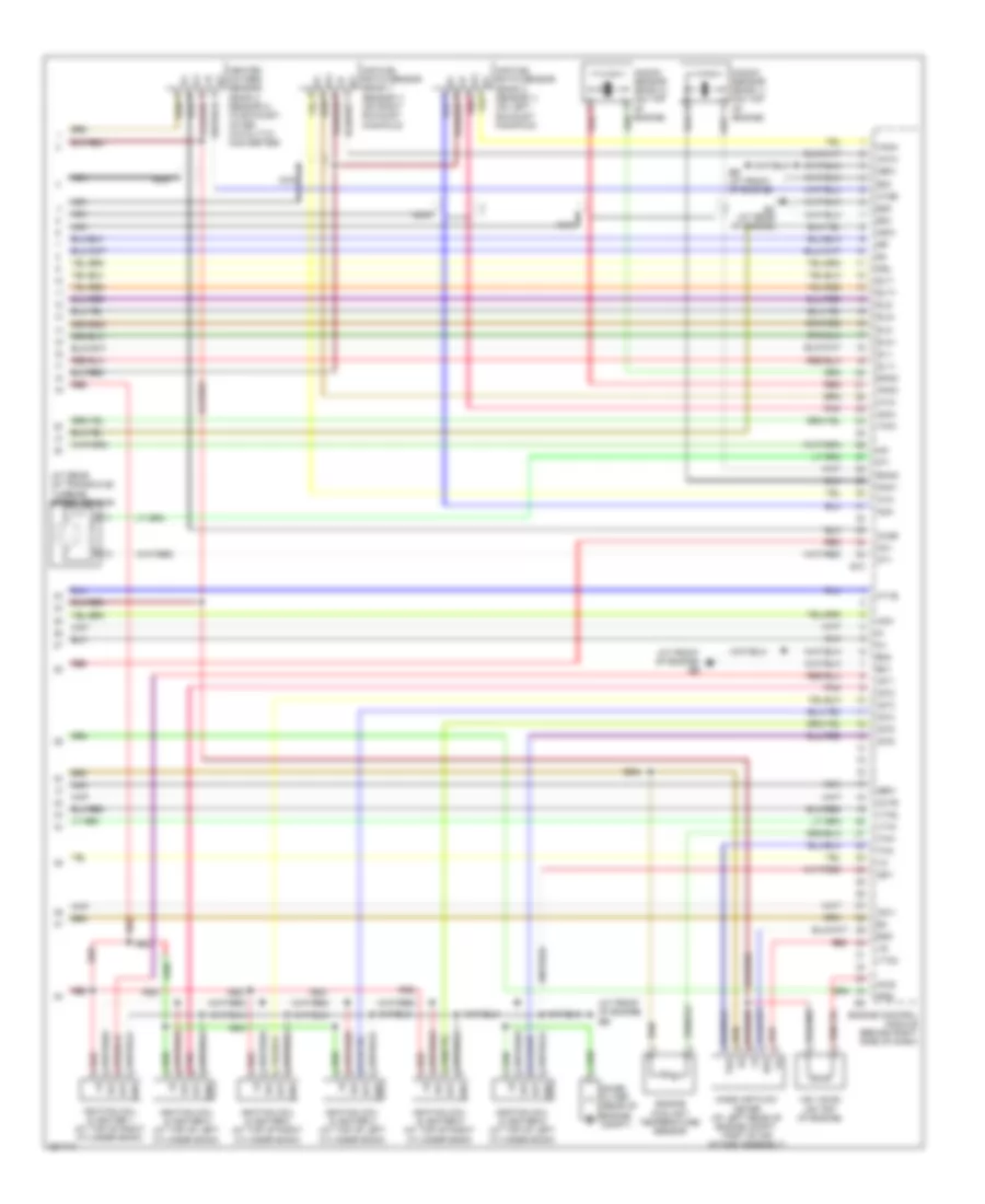
3.5L, Engine Performance Wiring Diagram (1 of 6) for Toyota Sienna LE 2009

List of elements for 3.5L, Engine Performance Wiring Diagram (1 of 6) for Toyota Sienna LE 2009:
- (at front of engine) eb
- (at left side of engine compt) ed
- (behind left end of dash) j/c 3 & 4
- (behind upper left side of dash) j/c 20
- +b2
- +bm
- A/f fuse 25a
- Accel position sensor (under left side of dash)
- Alt
- At4
- Atl
- Batt
- C/ opn relay
- Canh
- Canl
- Computer data lines system
- Efi 1 fuse 20a
- Efi 2 fuse 10a
- Efi relay
- Efii
- Efio
- Els
- Engine control module (behind right side of dash)
- Engine room j/b (on left side of engine compt)
- Eom
- Ep1
- Ep2
- Epa
- Epa2
- Etcs fuse 10a
- Fuel pump relay
- Hot at all times
- Igsw
- Ill
- Imi
- Imo
- Interior lights system
- J/c 18 (behind upper left side of dash)
- J/c 19 (behind upper left side of dash)
- J/c 21 (behind upper left center of dash)
- J/c 3 & 4 (behind left end of dash)
- J/c 48
- J/c 5 & 6 (behind left end of dash)
- J/c 5 & 6 (behind left end of dash) j5
- Mpmp
- Mrel
- Nssd
- Nssl
- Power distribution system
- Ppmp
- Red
- Spd
- St1-
- Starting/ charging system
- Stp
- Tach
- Transmission control switch (at base of shifter assembly)
- Transponder key computer (behind upper center of dash)
- Vcp1
- Vcp2
- Vcpa
- Vpa
- Vpa1
- Vpa2
- Vpmp
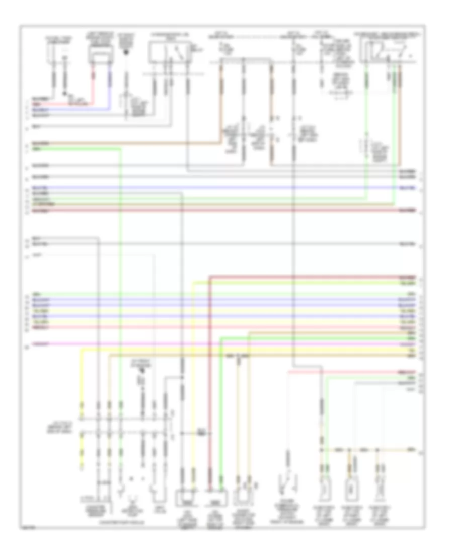
3.5L, Engine Performance Wiring Diagram (2 of 6) for Toyota Sienna LE 2009
List of elements for 3.5L, Engine Performance Wiring Diagram (2 of 6) for Toyota Sienna LE 2009:
- (at front of engine) eb
- (at right side of engine compt) ea
- (behind left end of dash) j/c 15
- (in engine room j/b) r/b 6
- (in fuel tank) fuel pump
- (left rear of engine compt) fuel pump resistor
- (on bracket, above brake pedal) stop light switch
- A/f relay
- Bh (at left "b" pillar)
- C16
- Canister pressure sensor
- Canister pump module
- Driver side j/b (behind dash, left of steering column)
- H13
- H18
- Hot at all times
- Hot in on or start
- Ign fuse 7.5a
- Inj fuse 10a
- Injector 4 (at top of left cylinder bank)
- Injector 5 (at top of right cylinder bank)
- Injector 6 (at top of left cylinder bank)
- J/c 1 (at left side of engine compt)
- J/c 13 & 14 (behind left end of dash)
- J/c 18 (behind upper left side of dash)
- J/c 2 (at left side of engine compt)
- J/c 3 & 4 (behind left end of dash)
- J/c 5 & 6 (behind left end of dash)
- J13
- J14
- K30
- Leak detection pump
- Power steering oil pressure switch (on right front of engine)
- Red
- S34
- S35
- Short connector s34 & s35 (right side of dash)
- Stop fuse 10a
- Vent valve
- Vsv (acm) (left side of engine compt)
- Vsv (purge) (on top right of engine)
3.5L, Engine Performance Wiring Diagram (3 of 6) for Toyota Sienna LE 2009
List of elements for 3.5L, Engine Performance Wiring Diagram (3 of 6) for Toyota Sienna LE 2009:
- (behind upper left side of dash) j/c 18
- (on transaxle) park/neutral position switch
- B pnk
- Diode (starter)
- Driver side j/b (behind dash, left of steering column)
- E11
- Eb (at front of engine)
- Engine control module (behind right side of dash)
- Ev1+
- Ev1-
- Ev2+
- Ev2-
- Fpr
- Fuse box (behind lower right side of dash)
- Gauge 1 fuse 10a
- Hot in on or start
- Hot in start
- Injector 1 (at top of right cylinder bank)
- Injector 2 (at top of left cylinder bank)
- Injector 3 (at top of right cylinder bank)
- J/c 20 (behind upper left side of dash)
- J/c 47
- J/c 48
- L26
- Left exhaust side camshaft timing oil control valve
- Ne+
- Ne-
- Oc1+
- Oc1-
- Oc2+
- Oc2-
- Oe1+
- Oe1-
- Oe2+
- Oe2-
- Pnk
- Pr2
- Psw
- Red
- Right exhaust side camshaft timing oil control valve
- St fuse 7.5a
- Sta
- Stsw
- Vv1+
- Vv1-
- Vv2+
- Vv2-
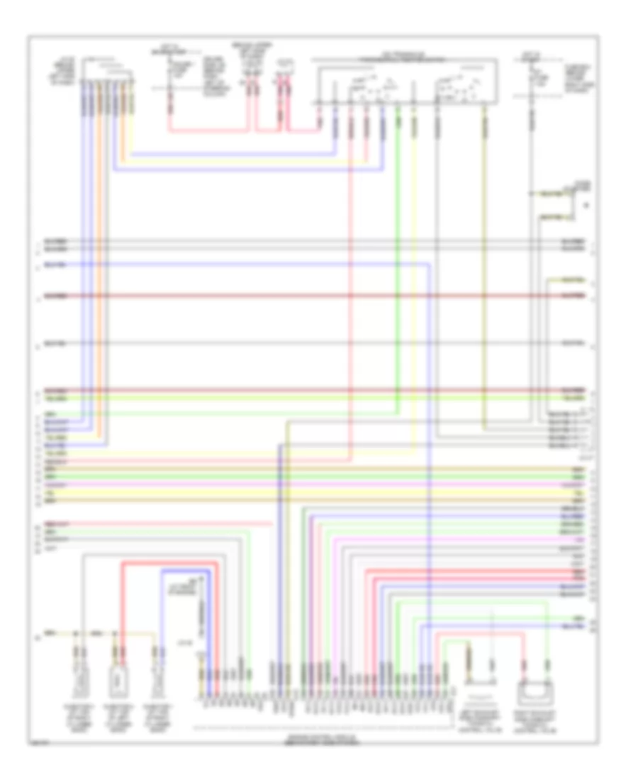
3.5L, Engine Performance Wiring Diagram (4 of 6) for Toyota Sienna LE 2009
List of elements for 3.5L, Engine Performance Wiring Diagram (4 of 6) for Toyota Sienna LE 2009:
- Bean ic
- Combination meter
- Computer data lines system
- Crankshaft position sensor
- Drive ic
- Eb (at front of engine)
- Ex+
- Ex-
- If (behind lower center of dash)
- Ig+
- J/c 19 (behind upper left side of dash)
- J/c 20 (behind upper left side of dash)
- J/c 48
- Left intake side camshaft timing oil control valve (top front of engine)
- Malfunction indicator lamp
- Micro computer
- Nca
- Pnk
- Red
- Right intake side camshaft timing oil control valve
- Speedometer
- Vc2
- Vsv (aciv) (at left rear of engine)
- Vvl+
- Vvl-
- Vvr+
- Vvr-
- Vvt sensor (bank 1 sensor 1) (top front of engine)
- Vvt sensor (bank 1 sensor 2) (top front of engine)
- Vvt sensor (bank 2 sensor 1) (top front of engine)
- Vvt sensor (bank 2 sensor 2) (top front of engine)
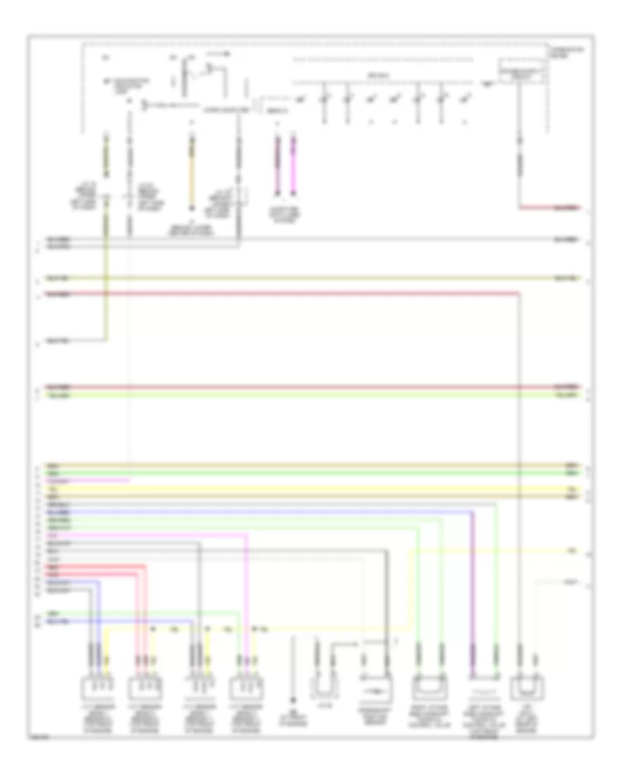
3.5L, Engine Performance Wiring Diagram (5 of 6) for Toyota Sienna LE 2009
List of elements for 3.5L, Engine Performance Wiring Diagram (5 of 6) for Toyota Sienna LE 2009:
- (at front of engine) eb
- (behind left end of dash) j/c 3 & 4
- Counter gear speed sensor (on top of transaxle)
- Driver side j/b (behind dash, left of steering column)
- Ed (at left side of engine compt)
- Electronically controlled transmission solenoid (on left side of transaxle)
- Gauge 2 fuse 7.5a
- H18
- H25
- Heated oxygen sensor (bank 1 sensor 2) (in exhaust)
- Hot at all times
- Hot in on or start
- Ig2 fuse 7.5a
- Ig2 relay
- Inj fuse 10a
- J/c 48
- Nca
- Noise filter (rear of engine compt)
- R/b 3 (in engine room j/b)
- Red
- Throttle position sensor & throttle control motor (throttle position sensor: on throttle body assembly) (throttle control motor: at left rear of engine compt)
- Vta1
- Vta2
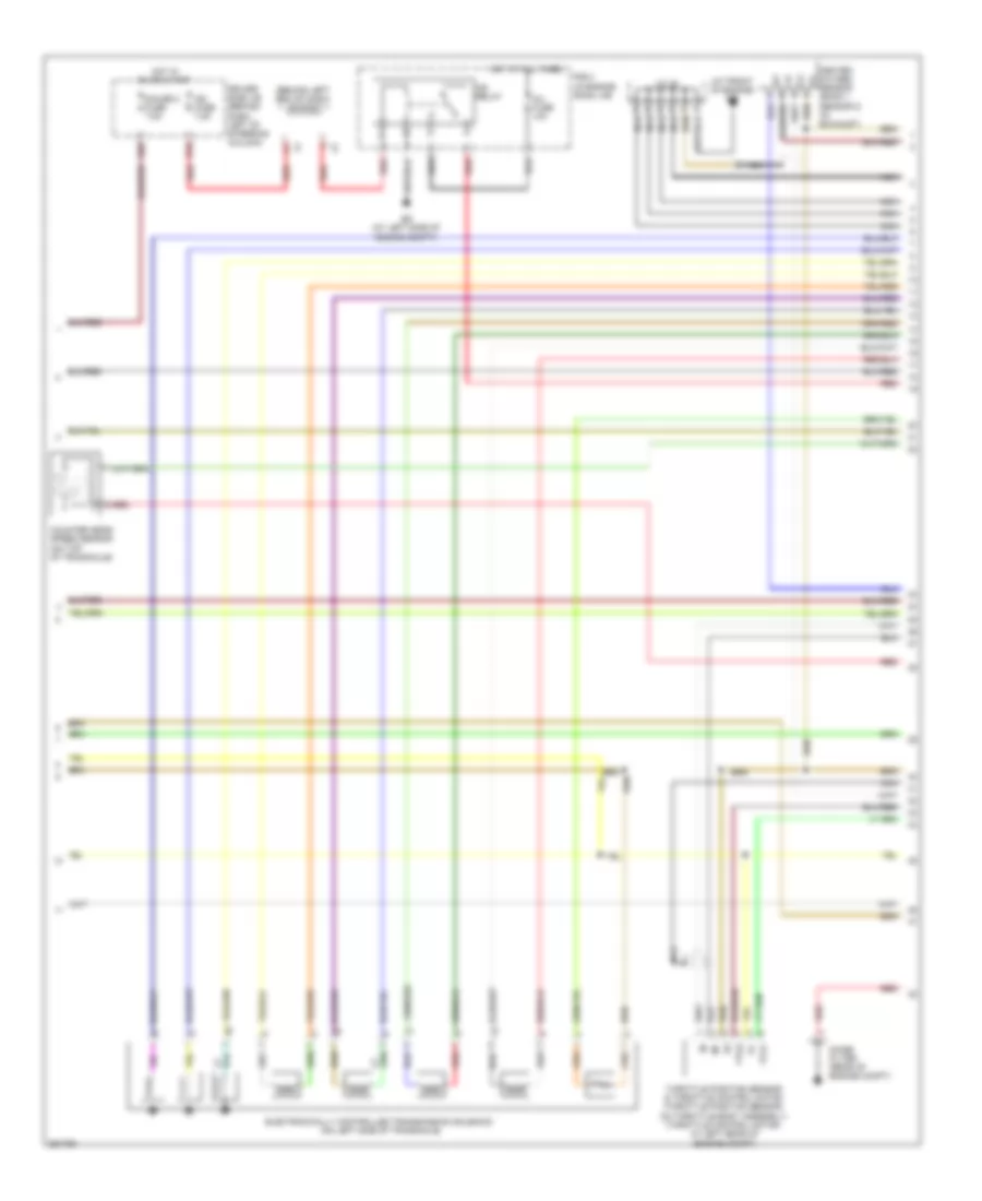
3.5L, Engine Performance Wiring Diagram (6 of 6) for Toyota Sienna LE 2009
List of elements for 3.5L, Engine Performance Wiring Diagram (6 of 6) for Toyota Sienna LE 2009:
- (at front of engine) eb
- (at rear of transaxle) turbine speed sensor
- A1a+
- A1a-
- A2a+
- A2a-
- Acis
- Aciv
- Acm
- Af+
- Af+ pnk
- Af-
- Air fuel ratio sensor (bank 1 sensor 1) (on right exhaust manifold)
- Air fuel ratio sensor (bank 2 sensor 1) (on left exhaust manifold)
- Dsl
- E01
- E02
- E03
- E04
- E05
- E10
- E2g
- Eb (at front of engine)
- Ec (at rear of engine)
- Ekn2
- Eknk
- Engine control module (behind right side of dash)
- Engine coolant temperature sensor
- Ge01
- Gnd
- Ha1a
- Ha2a
- Heated oxygen sensor (bank 2 sensor 2) (in exhaust, after catalytic converter)
- Ht1b
- Ht2b
- Igf1
- Ignition coil & igniter 1 (at top of right cylinder bank)
- Ignition coil & igniter 2 (at top of left cylinder bank)
- Ignition coil & igniter 3 (at top of right cylinder bank)
- Ignition coil & igniter 4 (at top of left cylinder bank)
- Ignition coil & igniter 5 (at top of right cylinder bank)
- Ignition coil & igniter 6 (at top of left cylinder bank)
- Igt1
- Igt2
- Igt3
- Igt4
- Igt5
- Igt6
- Knk1
- Knk2
- Knock sensor (bank 1) (on top of engine)
- Knock sensor (bank 2) (on top of engine)
- Mass air flow meter (at left rear of engine compt, part of air intake assembly)
- Me01
- Nc+
- Nc-
- Nca
- Noise filter (rear of engine compt)
- Nsw
- Nt+
- Nt-
- Ox1b
- Ox2b
- Pnk
- Pnk igt
- Prg
- Red
- Red +b
- Sl1+
- Sl1-
- Sl2+
- Sl2-
- Sl3+
- Sl3-
- Slt+
- Slt-
- Tha
- Tho1
- Thw
- Vsv (acis) (on top of engine)
- Vta1
- Vta2