ENGINE PERFORMANCE
2.4L
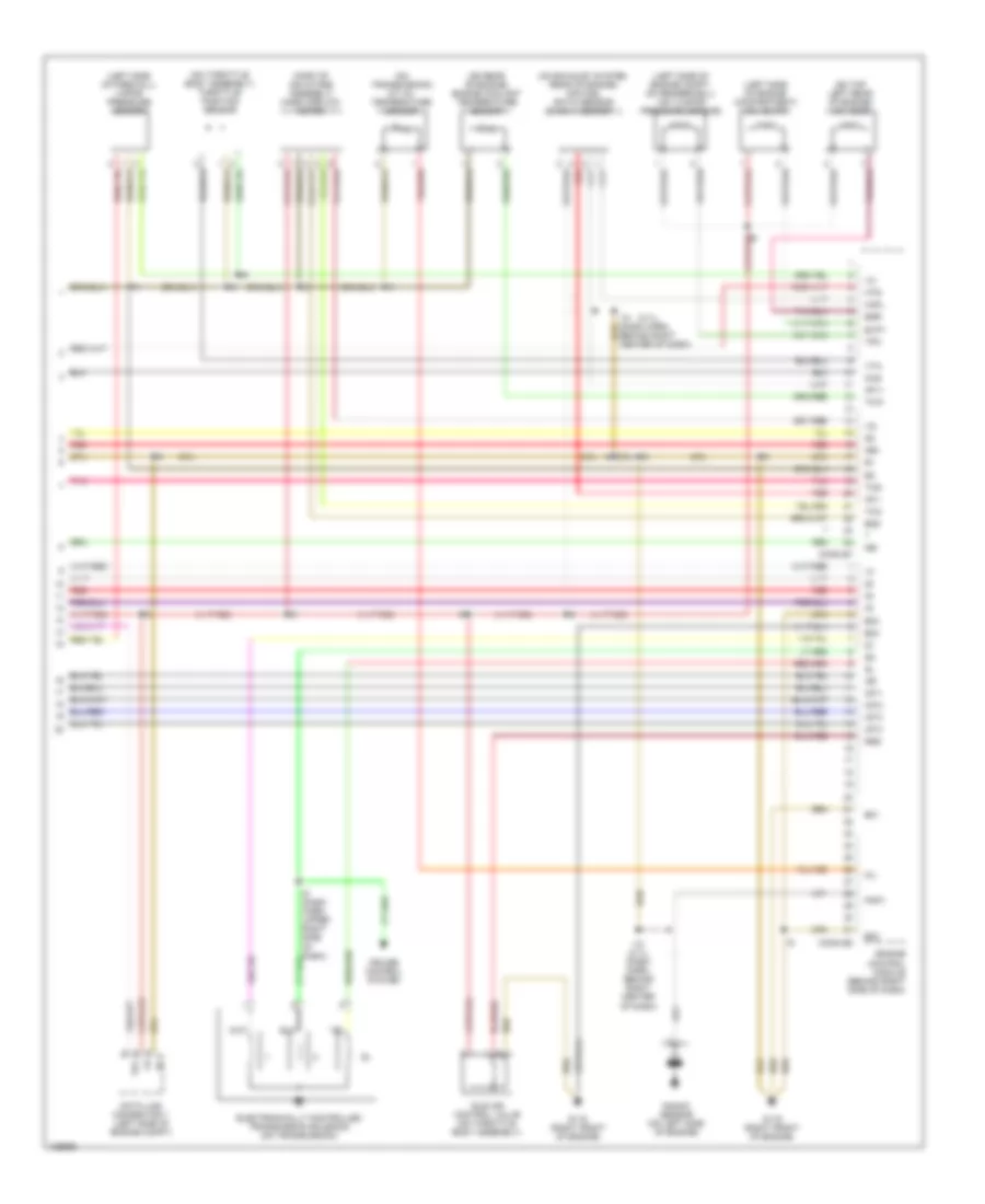
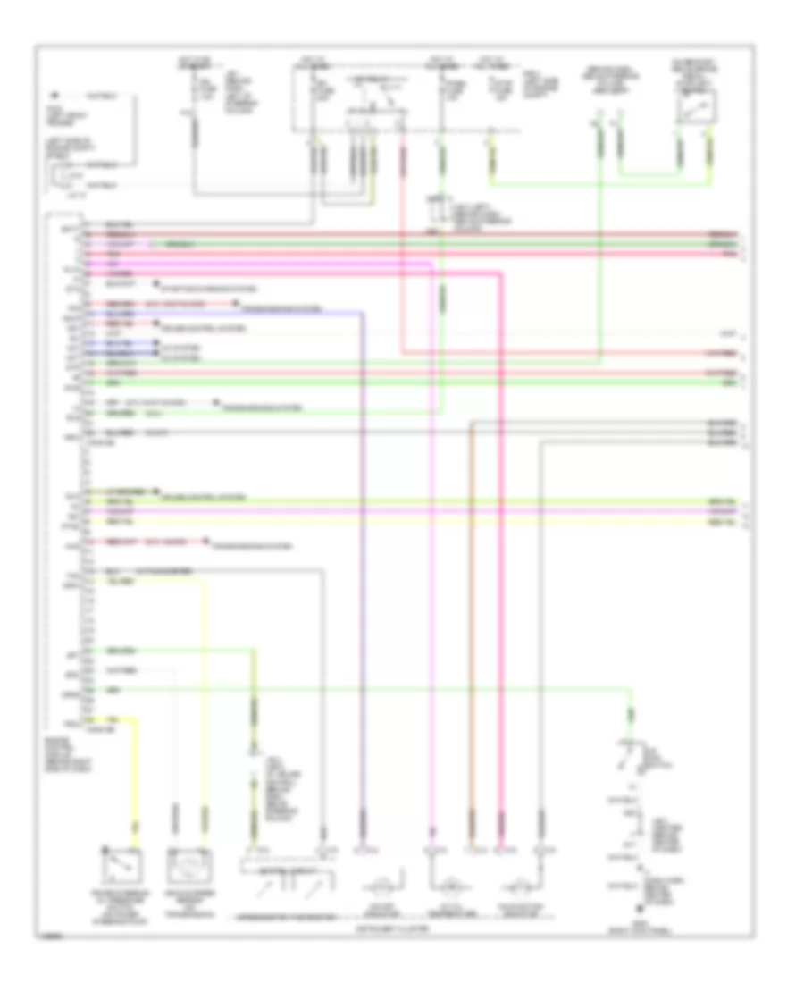
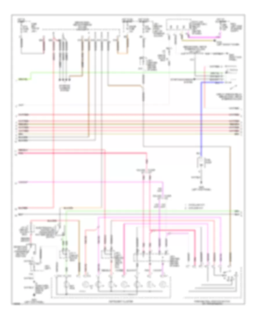
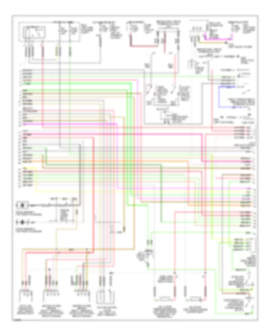
2.4L, Engine Performance Wiring Diagrams, California (1 of 4) for Toyota Tacoma 2000

List of elements for 2.4L, Engine Performance Wiring Diagrams, California (1 of 4) for Toyota Tacoma 2000:
- (2.4l)
- (2.7l w/4wd)
- (2.7l w/a/t & 4wd)
- (behind dash, above steering column) j/b 3 (left)
- (left side of engine compt) j/c 9,10
- (on bracket, above brake pedal) stoplight switch
- (w/a/t)
- (w/tachometer)
- 4wd
- A/c system
- A/t oil temperature
- Ac1
- Act
- Batt
- C10
- C12
- C13
- C16
- C20
- Conn e5
- Conn e6
- Control circuit
- Cruise control system
- Efi fuse 20a
- Efi relay
- Els
- Engine control module (behind right side of dash)
- G100 (left front fender)
- G17
- G203 (right kick panel)
- G22
- Hot at all times
- Hot in on or start
- I7 (dash harn, behind center of dash)
- Idlo
- Ign fuse 7.5a
- Instrument cluster
- J/b 1 (behind dash, left of steering column)
- J/b 3 (center) (behind center of dash)
- J/b 3 (left) (behind dash, above steering column)
- J/b 3 (left) (w/ cruise control) (behind dash, above steering column)
- J/c 10
- J/c 9
- Malfunction indicator
- Nsw
- O/d main switch
- O/d off indicator
- Od1
- Odlp
- Odms
- Oilw
- Panel fuse 10a
- Pnk
- Power steering oil pressure switch (on power steering pump)
- Psw
- Ptnk
- Pwr
- R/b 2 (left side of engine compt)
- Sil
- Sp1
- Sp2+
- Sp2-
- Speedometer
- Sta
- Starting/charging system
- Stop fuse 15a
- Stp
- Tac
- Tachometer
- Te1
- Tfn
- Transmissions system
- Vehicle speed sensor (on transmission)
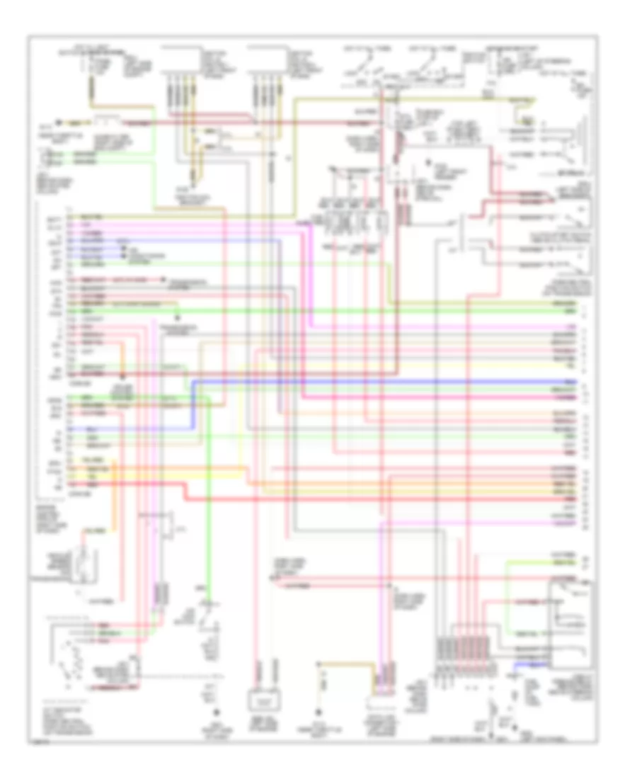
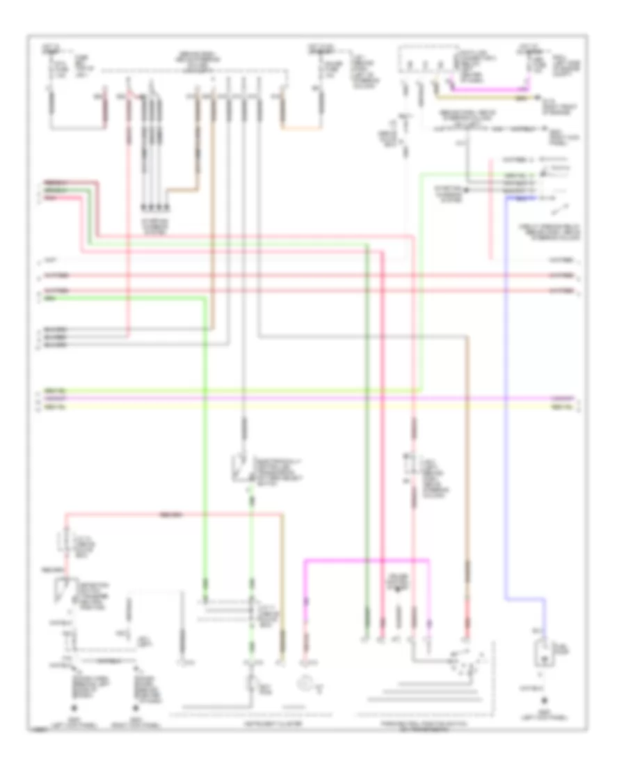
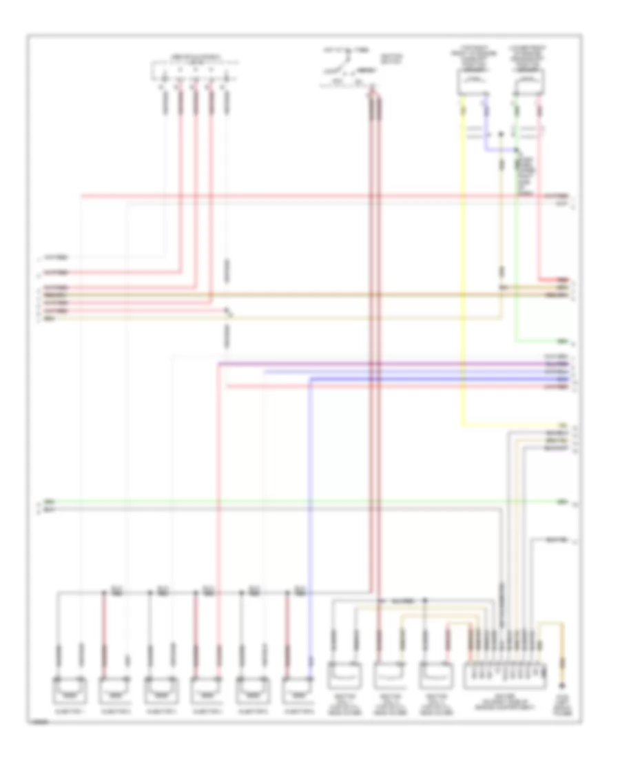
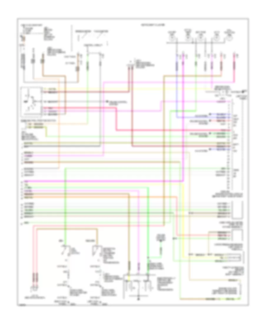
2.4L, Engine Performance Wiring Diagrams, California (2 of 4) for Toyota Tacoma 2000
List of elements for 2.4L, Engine Performance Wiring Diagrams, California (2 of 4) for Toyota Tacoma 2000:
- (2.7l w/m/t & 4wd)
- (behind dash, above steering column) j/b 3 (left)
- (w/a/t)
- (w/m/t)
- A/t p
- A14
- A15
- A16
- Batt
- C10
- C12
- C13
- Circuit opening relay (behind dash, above steering column)
- Cruise control system
- Data link connector 3 (below left center of dash)
- Detection switch (transfer neutral position)
- Ect pwr
- Electronically controlled transmission pattern select switch
- F12
- F16
- F20
- Fuel pump
- Fuse box (top of j/b 1)
- G119 (right front of engine)
- G200 (left kick panel)
- G203 (right kick panel)
- Gauge fuse 10a
- Hot at all times
- Hot in on or start
- Hot in start
- I6 (dash harn, behind left side of dash)
- Instrument cluster
- J/b 1 (behind dash, left of steering column)
- J/b 3 (left)
- J/b 3 (left) (behind dash, above steering column)
- J/c (above glove box)
- J/c 11 (above glove box)
- J/c 12 (above glove box)
- Obd fuse 10a
- Park/neutral position switch (on transmission)
- Pnk
- R/b 2 (left side of engine compt)
- Red
- Sil
- Sta fuse 7.5a
- Starting/ charging system
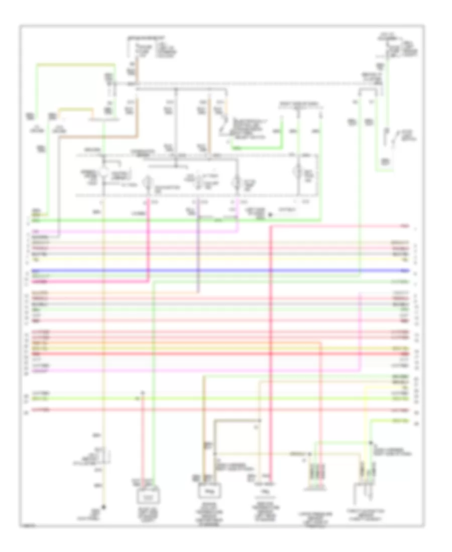
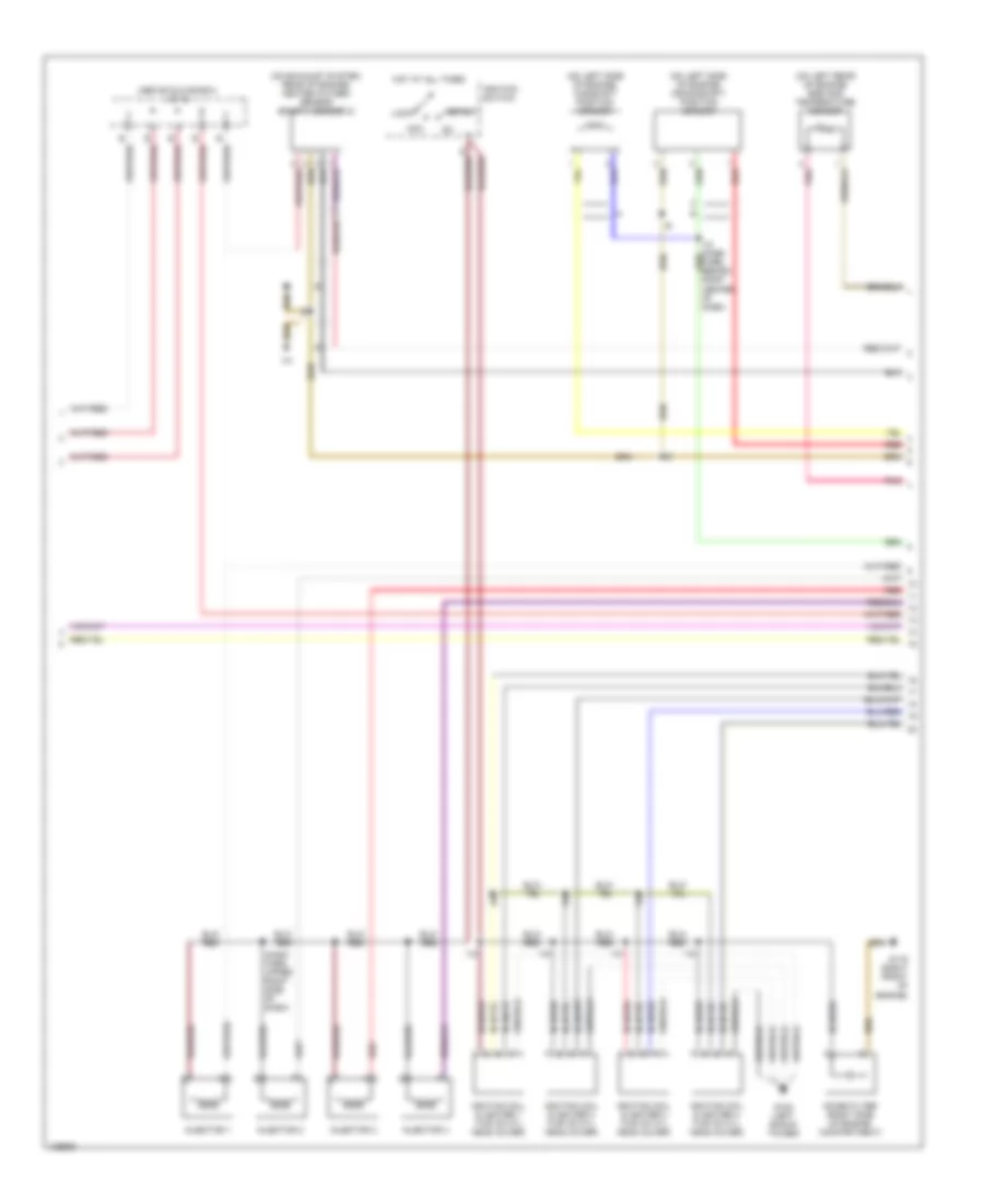
2.4L, Engine Performance Wiring Diagrams, California (3 of 4) for Toyota Tacoma 2000
List of elements for 2.4L, Engine Performance Wiring Diagrams, California (3 of 4) for Toyota Tacoma 2000:
- (above glove box) j/c 12
- (dash harn, upper right side of dash)
- (on exhaust system, rear of engine) heated oxygen sensor (bank 1, sensor 2)
- (on left rear of engine) egr gas temperature sensor
- (on left side of engine) camshaft position sensor
- (on left side of engine) crankshaft position sensor
- Acc
- G102 (left shock tower)
- G119 (right front of engine)
- Hot at all times
- I10
- Ignition coil & igniter 1 (top of cyl head cover)
- Ignition coil & igniter 2 (top of cyl head cover)
- Ignition coil & igniter 3 (top of cyl head cover)
- Ignition coil & igniter 4 (top of cyl head cover)
- Ignition switch
- Injector 1
- Injector 2
- Injector 3
- Injector 4
- Lock
- Noise filter (right side of engine compartment)
- Pnk
- Red
- Start
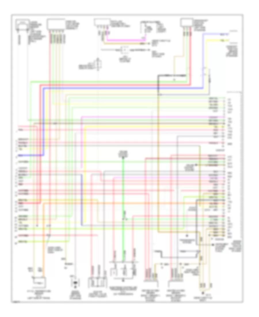
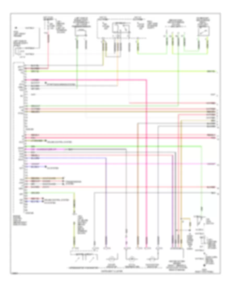
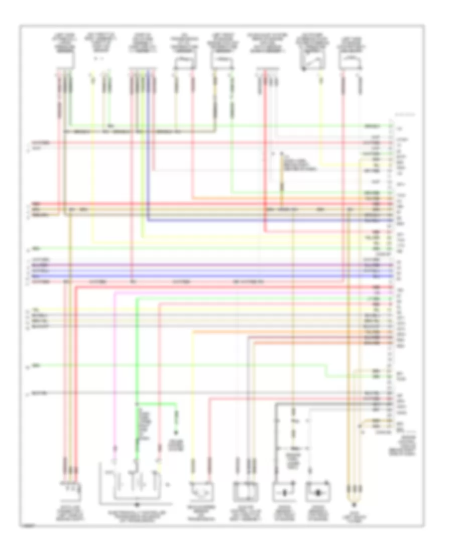
2.4L, Engine Performance Wiring Diagrams, California (4 of 4) for Toyota Tacoma 2000
List of elements for 2.4L, Engine Performance Wiring Diagrams, California (4 of 4) for Toyota Tacoma 2000:
- (2.7l)
- (left side of engine compartment) vsv (evap)
- (left side of engine compt, on fenderwell) vsv (vapor pressure sensor)
- (left side of firewall) vapor pressure sensor
- (on exhaust system, rear of engine) air fuel ratio sensor (bank 1, sensor 1)
- (on rear of engine) engine coolant temperature sensor
- (on throttle body assembly) throttle position sensor
- (on top left rear of engine) vsv (egr)
- (on transmission) a/t oil temperature sensor
- (part of air intake assembly) mass airflow meter
- Af1+
- Af1-
- Behind right center of dash)
- Conn e7
- Conn e8
- Cruise control system
- Data link connector 1 (left side of engine compt)
- E01
- E02
- E03
- E04
- E2g
- Egr
- Electronically controlled transmission solenoid (on transmission)
- Engine control module (behind right side of dash)
- Evp1
- G119 (right front of engine)
- Hafl
- Hts
- I10 (2.7l) (dash harn, behind right center of dash)
- I9 (dash harn, upper right side of dash)
- Idle air control valve (on throttle body assembly)
- Igf
- Igt1
- Igt2
- Igt3
- Igt4
- Knk1
- Knock sensor (on left side of engine)
- Ne+
- Ne-
- Oil
- Oxs
- Pnk
- Red
- Rsd
- Te1
- Tha
- Thg
- Thw
- Tpc
- Vta
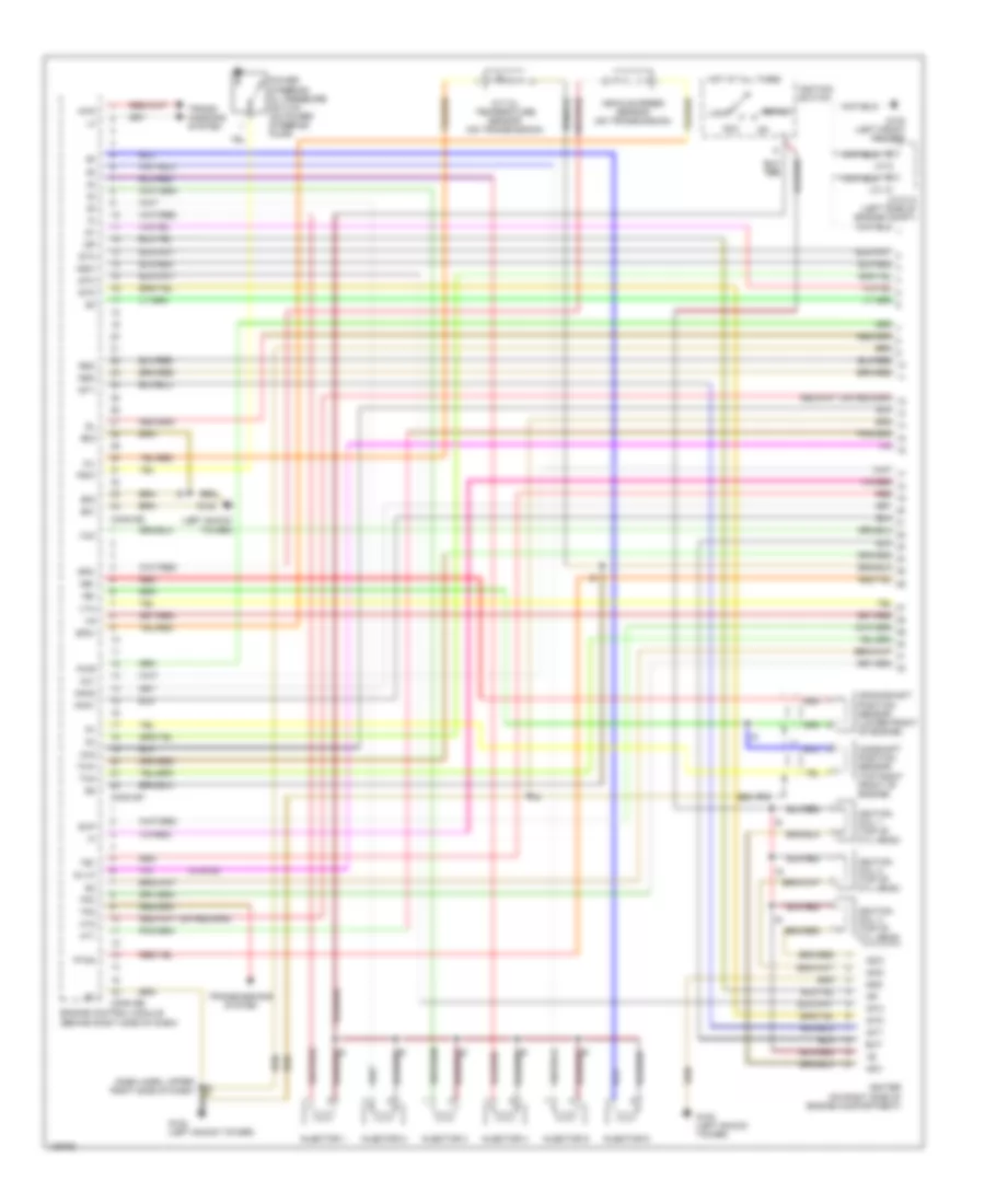
2.4L, Engine Performance Wiring Diagrams, Except California (1 of 3) for Toyota Tacoma 2000
List of elements for 2.4L, Engine Performance Wiring Diagrams, Except California (1 of 3) for Toyota Tacoma 2000:
- (2.4l)
- (2.7l w/ 4wd)
- (2.7l w/a/t & 4wd)
- (2.7l)
- (dash harn, right side of dash) i9
- (ignition coil bracket)
- (near throttle body)
- (right side of dash)
- (top left of battery) j/c 9, j/c 10
- (w/a/t)
- 2.4l
- 2.7l
- 4wd
- A/t
- A/t indicator switch (park neutral position switch) (on transmission)
- A14
- A16
- Acc
- Aci
- Act
- Air conditioning system
- Batt
- C16
- C20
- Circuit opening relay (behind dash above steering column)
- Clutch start switch (above clutch pedal)
- Conn e5
- Conn e6
- Cruise control system
- Data link connector 1 (left side of engine)
- E20
- E21
- E22
- Efi fuse 15a
- Efi relay
- Egr vsv (left side of engine)
- Els
- Engine control module (right side of dash)
- F15
- Fuel injectors
- Fuel pump (in fuel tank)
- Fuse box (top of j/b 1)
- G102 (left front fender)
- G113
- G113 (near throttle body)
- G125
- G17
- G201
- G201 (right side of dash)
- G202 (left kick panel)
- G22
- Hot at all times
- Hot in on or start
- Hot w/ light switch in head or park
- I9 (dash harn, right side of dash)
- Ig2
- Ign fuse 7.5a
- Ignition coil & ignitor 1 (left front of eng)
- Ignition coil & ignitor 2 (left front of eng)
- Ignition switch
- J/b 1 (left of steering column)
- J/b 3 (behind dash above strg col)
- J/b 3 (behind dash above strg column)
- J/b 3 (behind dash, above strg column)
- Lock
- M/t
- Ne-
- Noise filter (right side of eng compt)
- Nsw
- O/d main switch
- Od1
- Odlp
- Odms
- Oil-w
- Panel fuse 10a
- Park/neutral position switch (on transmission)
- Pnk
- Ptnk
- Pwr
- R/b 2 (left side of eng compt)
- R/b 2 (left side of engine compt)
- Red
- Red/
- Sil
- Sp1
- Sp2+
- Sp2-
- St1
- Sta
- Sta fuse 7.5a
- Start
- Tfn
- Transmission system
- Transmission)
- Vehicle speed sensor (on
2.4L, Engine Performance Wiring Diagrams, Except California (2 of 3) for Toyota Tacoma 2000
List of elements for 2.4L, Engine Performance Wiring Diagrams, Except California (2 of 3) for Toyota Tacoma 2000:
- (behind i/p cluster) j/b 3
- (left side of dash) g202
- (right side of dash) j/c 11
- 2.7l
- A/t oil temp ind.
- C10
- C12
- C13
- Combination meter
- Control circuit
- D13
- D18
- D19
- D20
- E14
- E16
- Ect pwr ind.
- Egr gas temperature sensor (left rear of engine)
- Electronically controlled transmission pattern select switch
- Engine coolant temperature sensor (center rear of engine)
- Evap vsv (left side of engine compt)
- G200 (left kick panel)
- Gauge fuse 10a
- Hot at all times
- Hot in on or start
- I9 (dash harness, right side of dash)
- J/b 1 (left of steering column)
- J/b 3 (behind i/p cluster)
- Malfunction ind.
- O/d off ind.
- Pnk
- R/b 2 (left engine compt)
- Red
- Speedo- meter w/o tach
- Stop fuse 15a
- Stop- light switch
- Throttle position sensor (throttle body)
- Vapor pressure sensor (left side of firewall)
- W/ cruise
- W/ tach
- W/o cruise
- W/o tach
2.4L, Engine Performance Wiring Diagrams, Except California (3 of 3) for Toyota Tacoma 2000
List of elements for 2.4L, Engine Performance Wiring Diagrams, Except California (3 of 3) for Toyota Tacoma 2000:
- (2.7l)
- (dash harn, right side of dash)
- (near throttle body)
- (near throttle body) g113
- (w/a/t & 4wd)
- A/t oil temperature sensor (2.7l) (left side of trans)
- A15
- A16
- Camshaft position sensor (left side of engine)
- Conn e7
- Conn e8
- Crankshaft position sensor (left side of engine)
- Cruise control system
- Data link connector 3 (center of dash)
- E01
- Egr
- Electronic controlled transmission solenoid (2.7l) (on transmission)
- Engine control module (right side of dash)
- Eo2
- Eo3
- Evp
- G113
- G201 (right side of dash)
- Heated oxygen sensor (bank 1 sensor 1) (exhaust system)
- Heated oxygen sensor (bank 1 sensor 2) (exhaust system)
- Hot at all times
- Ht1
- Ht2
- I9 (dash harn, right side of dash)
- Idle air control valve (throttle body)
- Idlo
- Igf
- Igt1
- Igt2
- Instrument cluster system (tach)
- J/b 3 (behind i/p cluster)
- J/c 11 (behind right side of dash)
- Knk
- Knock sensor (left side of engine)
- Mass air- flow meter (air intake assembly)
- Nca
- Obd fuse 10a
- Oil
- Ox1
- Ox2
- Pnk
- R/b 2 (left engine compt)
- Red
- Rsc
- Rso
- Tac
- Te1
- Tha
- Thg
- Thw
- Tpc
- Transmission system
- Vapor pressure sensor vsv (left side of engine compartment, on fender- well)
- Vta
2.7L
2.7L, Engine Performance Wiring Diagrams, California (1 of 4) for Toyota Tacoma 2000
List of elements for 2.7L, Engine Performance Wiring Diagrams, California (1 of 4) for Toyota Tacoma 2000:
- (2.4l)
- (2.7l w/4wd)
- (2.7l w/a/t & 4wd)
- (behind dash, above steering column) j/b 3 (left)
- (left side of engine compt) j/c 9,10
- (on bracket, above brake pedal) stoplight switch
- (w/a/t)
- (w/tachometer)
- 4wd
- A/c system
- A/t oil temperature
- Ac1
- Act
- Batt
- C10
- C12
- C13
- C16
- C20
- Conn e5
- Conn e6
- Control circuit
- Cruise control system
- Efi fuse 20a
- Efi relay
- Els
- Engine control module (behind right side of dash)
- G100 (left front fender)
- G17
- G203 (right kick panel)
- G22
- Hot at all times
- Hot in on or start
- I7 (dash harn, behind center of dash)
- Idlo
- Ign fuse 7.5a
- Instrument cluster
- J/b 1 (behind dash, left of steering column)
- J/b 3 (center) (behind center of dash)
- J/b 3 (left) (behind dash, above steering column)
- J/b 3 (left) (w/ cruise control) (behind dash, above steering column)
- J/c 10
- J/c 9
- Malfunction indicator
- Nsw
- O/d main switch
- O/d off indicator
- Od1
- Odlp
- Odms
- Oilw
- Panel fuse 10a
- Pnk
- Power steering oil pressure switch (on power steering pump)
- Psw
- Ptnk
- Pwr
- R/b 2 (left side of engine compt)
- Sil
- Sp1
- Sp2+
- Sp2-
- Speedometer
- Sta
- Starting/charging system
- Stop fuse 15a
- Stp
- Tac
- Tachometer
- Te1
- Tfn
- Transmissions system
- Vehicle speed sensor (on transmission)
2.7L, Engine Performance Wiring Diagrams, California (2 of 4) for Toyota Tacoma 2000
List of elements for 2.7L, Engine Performance Wiring Diagrams, California (2 of 4) for Toyota Tacoma 2000:
- (2.7l w/m/t & 4wd)
- (behind dash, above steering column) j/b 3 (left)
- (w/a/t)
- (w/m/t)
- A/t p
- A14
- A15
- A16
- Batt
- C10
- C12
- C13
- Circuit opening relay (behind dash, above steering column)
- Cruise control system
- Data link connector 3 (below left center of dash)
- Detection switch (transfer neutral position)
- Ect pwr
- Electronically controlled transmission pattern select switch
- F12
- F16
- F20
- Fuel pump
- Fuse box (top of j/b 1)
- G119 (right front of engine)
- G200 (left kick panel)
- G203 (right kick panel)
- Gauge fuse 10a
- Hot at all times
- Hot in on or start
- Hot in start
- I6 (dash harn, behind left side of dash)
- Instrument cluster
- J/b 1 (behind dash, left of steering column)
- J/b 3 (left)
- J/b 3 (left) (behind dash, above steering column)
- J/c (above glove box)
- J/c 11 (above glove box)
- J/c 12 (above glove box)
- Obd fuse 10a
- Park/neutral position switch (on transmission)
- Pnk
- R/b 2 (left side of engine compt)
- Red
- Sil
- Sta fuse 7.5a
- Starting/ charging system
2.7L, Engine Performance Wiring Diagrams, California (3 of 4) for Toyota Tacoma 2000
List of elements for 2.7L, Engine Performance Wiring Diagrams, California (3 of 4) for Toyota Tacoma 2000:
- (above glove box) j/c 12
- (dash harn, upper right side of dash)
- (on exhaust system, rear of engine) heated oxygen sensor (bank 1, sensor 2)
- (on left rear of engine) egr gas temperature sensor
- (on left side of engine) camshaft position sensor
- (on left side of engine) crankshaft position sensor
- Acc
- G102 (left shock tower)
- G119 (right front of engine)
- Hot at all times
- I10
- Ignition coil & igniter 1 (top of cyl head cover)
- Ignition coil & igniter 2 (top of cyl head cover)
- Ignition coil & igniter 3 (top of cyl head cover)
- Ignition coil & igniter 4 (top of cyl head cover)
- Ignition switch
- Injector 1
- Injector 2
- Injector 3
- Injector 4
- Lock
- Noise filter (right side of engine compartment)
- Pnk
- Red
- Start
2.7L, Engine Performance Wiring Diagrams, California (4 of 4) for Toyota Tacoma 2000
List of elements for 2.7L, Engine Performance Wiring Diagrams, California (4 of 4) for Toyota Tacoma 2000:
- (2.7l)
- (left side of engine compartment) vsv (evap)
- (left side of engine compt, on fenderwell) vsv (vapor pressure sensor)
- (left side of firewall) vapor pressure sensor
- (on exhaust system, rear of engine) air fuel ratio sensor (bank 1, sensor 1)
- (on rear of engine) engine coolant temperature sensor
- (on throttle body assembly) throttle position sensor
- (on top left rear of engine) vsv (egr)
- (on transmission) a/t oil temperature sensor
- (part of air intake assembly) mass airflow meter
- Af1+
- Af1-
- Behind right center of dash)
- Conn e7
- Conn e8
- Cruise control system
- Data link connector 1 (left side of engine compt)
- E01
- E02
- E03
- E04
- E2g
- Egr
- Electronically controlled transmission solenoid (on transmission)
- Engine control module (behind right side of dash)
- Evp1
- G119 (right front of engine)
- Hafl
- Hts
- I10 (2.7l) (dash harn, behind right center of dash)
- I9 (dash harn, upper right side of dash)
- Idle air control valve (on throttle body assembly)
- Igf
- Igt1
- Igt2
- Igt3
- Igt4
- Knk1
- Knock sensor (on left side of engine)
- Ne+
- Ne-
- Oil
- Oxs
- Pnk
- Red
- Rsd
- Te1
- Tha
- Thg
- Thw
- Tpc
- Vta
2.7L, Engine Performance Wiring Diagrams, Except California (1 of 3) for Toyota Tacoma 2000
List of elements for 2.7L, Engine Performance Wiring Diagrams, Except California (1 of 3) for Toyota Tacoma 2000:
- (2.4l)
- (2.7l w/ 4wd)
- (2.7l w/a/t & 4wd)
- (2.7l)
- (dash harn, right side of dash) i9
- (ignition coil bracket)
- (near throttle body)
- (right side of dash)
- (top left of battery) j/c 9, j/c 10
- (w/a/t)
- 2.4l
- 2.7l
- 4wd
- A/t
- A/t indicator switch (park neutral position switch) (on transmission)
- A14
- A16
- Acc
- Aci
- Act
- Air conditioning system
- Batt
- C16
- C20
- Circuit opening relay (behind dash above steering column)
- Clutch start switch (above clutch pedal)
- Conn e5
- Conn e6
- Cruise control system
- Data link connector 1 (left side of engine)
- E20
- E21
- E22
- Efi fuse 15a
- Efi relay
- Egr vsv (left side of engine)
- Els
- Engine control module (right side of dash)
- F15
- Fuel injectors
- Fuel pump (in fuel tank)
- Fuse box (top of j/b 1)
- G102 (left front fender)
- G113
- G113 (near throttle body)
- G125
- G17
- G201
- G201 (right side of dash)
- G202 (left kick panel)
- G22
- Hot at all times
- Hot in on or start
- Hot w/ light switch in head or park
- I9 (dash harn, right side of dash)
- Ig2
- Ign fuse 7.5a
- Ignition coil & ignitor 1 (left front of eng)
- Ignition coil & ignitor 2 (left front of eng)
- Ignition switch
- J/b 1 (left of steering column)
- J/b 3 (behind dash above strg col)
- J/b 3 (behind dash above strg column)
- J/b 3 (behind dash, above strg column)
- Lock
- M/t
- Ne-
- Noise filter (right side of eng compt)
- Nsw
- O/d main switch
- Od1
- Odlp
- Odms
- Oil-w
- Panel fuse 10a
- Park/neutral position switch (on transmission)
- Pnk
- Ptnk
- Pwr
- R/b 2 (left side of eng compt)
- R/b 2 (left side of engine compt)
- Red
- Red/
- Sil
- Sp1
- Sp2+
- Sp2-
- St1
- Sta
- Sta fuse 7.5a
- Start
- Tfn
- Transmission system
- Transmission)
- Vehicle speed sensor (on
2.7L, Engine Performance Wiring Diagrams, Except California (2 of 3) for Toyota Tacoma 2000
List of elements for 2.7L, Engine Performance Wiring Diagrams, Except California (2 of 3) for Toyota Tacoma 2000:
- (behind i/p cluster) j/b 3
- (left side of dash) g202
- (right side of dash) j/c 11
- 2.7l
- A/t oil temp ind.
- C10
- C12
- C13
- Combination meter
- Control circuit
- D13
- D18
- D19
- D20
- E14
- E16
- Ect pwr ind.
- Egr gas temperature sensor (left rear of engine)
- Electronically controlled transmission pattern select switch
- Engine coolant temperature sensor (center rear of engine)
- Evap vsv (left side of engine compt)
- G200 (left kick panel)
- Gauge fuse 10a
- Hot at all times
- Hot in on or start
- I9 (dash harness, right side of dash)
- J/b 1 (left of steering column)
- J/b 3 (behind i/p cluster)
- Malfunction ind.
- O/d off ind.
- Pnk
- R/b 2 (left engine compt)
- Red
- Speedo- meter w/o tach
- Stop fuse 15a
- Stop- light switch
- Throttle position sensor (throttle body)
- Vapor pressure sensor (left side of firewall)
- W/ cruise
- W/ tach
- W/o cruise
- W/o tach
2.7L, Engine Performance Wiring Diagrams, Except California (3 of 3) for Toyota Tacoma 2000
List of elements for 2.7L, Engine Performance Wiring Diagrams, Except California (3 of 3) for Toyota Tacoma 2000:
- (2.7l)
- (dash harn, right side of dash)
- (near throttle body)
- (near throttle body) g113
- (w/a/t & 4wd)
- A/t oil temperature sensor (2.7l) (left side of trans)
- A15
- A16
- Camshaft position sensor (left side of engine)
- Conn e7
- Conn e8
- Crankshaft position sensor (left side of engine)
- Cruise control system
- Data link connector 3 (center of dash)
- E01
- Egr
- Electronic controlled transmission solenoid (2.7l) (on transmission)
- Engine control module (right side of dash)
- Eo2
- Eo3
- Evp
- G113
- G201 (right side of dash)
- Heated oxygen sensor (bank 1 sensor 1) (exhaust system)
- Heated oxygen sensor (bank 1 sensor 2) (exhaust system)
- Hot at all times
- Ht1
- Ht2
- I9 (dash harn, right side of dash)
- Idle air control valve (throttle body)
- Idlo
- Igf
- Igt1
- Igt2
- Instrument cluster system (tach)
- J/b 3 (behind i/p cluster)
- J/c 11 (behind right side of dash)
- Knk
- Knock sensor (left side of engine)
- Mass air- flow meter (air intake assembly)
- Nca
- Obd fuse 10a
- Oil
- Ox1
- Ox2
- Pnk
- R/b 2 (left engine compt)
- Red
- Rsc
- Rso
- Tac
- Te1
- Tha
- Thg
- Thw
- Tpc
- Transmission system
- Vapor pressure sensor vsv (left side of engine compartment, on fender- well)
- Vta
3.4L
3.4L, Engine Performance Wiring Diagrams, California (1 of 4) for Toyota Tacoma 2000
List of elements for 3.4L, Engine Performance Wiring Diagrams, California (1 of 4) for Toyota Tacoma 2000:
- (behind dash, above steering column) j/b 3 (left)
- (left side of engine compt) j/c 9,10
- (left side of engine compt, on fenderwell) vsv (vapor pressure sensor)
- (on bracket, above brake pedal) stoplight switch
- (w/4wd & floor a/t)
- (w/4wd)
- (w/a/t & 4wd)
- (w/a/t)
- 10 (or 3)
- 4wd
- 5 (or 1)
- A/c system
- A/t oil temperature
- Ac1
- Act
- Batt
- C10
- C12
- C13
- Conn e5
- Conn e6
- Control circuit
- Cruise control system
- Efi fuse 20a
- Efi relay
- Engine control module (behind right side of dash)
- G100 (left front fender)
- G17
- G203 (right kick panel)
- G22
- Heated oxygen sensor (bank 1, sensor 2) (on exhaust system, rear of engine)
- Hot at all times
- Hot in on or start
- Hts
- I7 (dash harn, behind center of dash)
- I9 (dash harn, upper right side of dash)
- Idlo
- Ign fuse 7.5a
- Igsw
- Instrument cluster
- J/b 1 (behind dash, left of steering column)
- J/b 3 (center) (behind center of dash)
- J/b 3 (left) (w/ cruise control) (behind dash, above steering column)
- J/c 10
- J/c 9
- Malfunction indicator
- Mrel
- Nsw
- O/d main switch
- O/d off indicator
- Od1
- Odlp
- Odms
- Oilw
- Oxs
- Pnk
- Ptnk
- R/b 2 (left side of engine compt)
- Sil
- Sp1
- Speedometer
- Sta
- Starting/charging system
- Stop fuse 15a
- Stp
- Tachometer
- Tfn
- Tpc
- Transmissions system
3.4L, Engine Performance Wiring Diagrams, California (2 of 4) for Toyota Tacoma 2000
List of elements for 3.4L, Engine Performance Wiring Diagrams, California (2 of 4) for Toyota Tacoma 2000:
- (behind dash, above steering column) j/b 3 (left)
- (w/a/t)
- (w/column a/t)
- (w/floor a/t)
- (w/m/t & 4wd)
- (w/m/t)
- A/t p
- A14
- A15
- A16
- Batt
- C10
- C11
- C12
- C13
- Cig fuse 15a
- Circuit opening relay (behind dash, above steering column)
- Column a/t
- Data link connector 3 (below left center of dash)
- Detection switch (transfer neutral position)
- Ect pwr
- Electronically controlled transmission pattern select switch
- F12
- F16
- F20
- Floor a/t
- Fuel pump
- Fuse box (top of j/b 1)
- G10
- G102 (left shock tower)
- G200 (left kick panel)
- G203 (right kick panel)
- Gauge fuse 10a
- H20
- H22
- Hot at all times
- Hot in on or accy
- Hot in on or start
- Hot in start
- I6 (dash harn, behind left side of dash)
- Instrument cluster
- J/b 1 (behind dash, left of steering column)
- J/b 3 (center) (behind center of dash)
- J/b 3 (left)
- J/b 3 (left) (behind dash, above str col)
- J/c (above glove box)
- J/c 11 (above glove box)
- J/c 12 (above glove box)
- Obd fuse 10a
- Park/neutral position switch (on transmission)
- Pnk
- R/b 2 (left side of engine compt)
- Sil
- Sta fuse 7.5a
- Starting/ charging system
- Starting/charging system
3.4L, Engine Performance Wiring Diagrams, California (3 of 4) for Toyota Tacoma 2000
List of elements for 3.4L, Engine Performance Wiring Diagrams, California (3 of 4) for Toyota Tacoma 2000:
- (above glove box) j/c 12
- (lower front of engine) crankshaft position sensor
- (top right front of engine) camshaft position sensor
- (w/ tachometer)
- Acc
- G102 (left shock tower)
- Gnd
- Hot at all times
- Igc1
- Igc2
- Igc3
- Igf
- Igniter (on right side of engine compartment)
- Ignition coil 1 (top of cyl head cover)
- Ignition coil 2 (top of cyl head cover)
- Ignition coil 3 (top of cyl head cover)
- Ignition switch
- Igt1
- Igt2
- Igt3
- Injector 1
- Injector 2
- Injector 3
- Injector 4
- Injector 5
- Injector 6
- Lock
- Red
- Start
- Tach
3.4L, Engine Performance Wiring Diagrams, California (4 of 4) for Toyota Tacoma 2000
List of elements for 3.4L, Engine Performance Wiring Diagrams, California (4 of 4) for Toyota Tacoma 2000:
- (engine harn, under r/b 2)
- (left front of engine) engine coolant temperature sensor
- (left side of engine compartment) vsv (evap)
- (left side of firewall) vapor pressure sensor
- (on exhaust system, rear of engine) air fuel ratio sensor (bank 1, sensor 1)
- (on power steering pump) power steering oil pressure switch
- (on throttle body assembly) throttle position sensor
- (on transmission) a/t oil temperature sensor
- (part of air intake assembly) mass airflow meter
- Af1+
- Af1-
- Conn e7
- Conn e8
- Cruise control system
- Data link connector 1 (left side of engine compt)
- E01
- E02
- E03
- E05
- E2g
- Electronically controlled transmission solenoid (on transmission)
- Engine control module (behind right side of dash)
- Evp1
- G102 (left shock tower)
- Htaf1
- I10 (dash harn, behind right center of dash)
- I9 (dash harn, upper right side of dash)
- Idle air control valve (on throttle body assembly)
- Igf
- Igt1
- Igt2
- Igt3
- Knk1
- Knk2
- Knock sensor 1 (top front of engine)
- Knock sensor 2 (top front of engine)
- Ne+
- Ne-
- Oil
- Psw
- Pwr
- Red
- Rsc
- Rso
- Sp2+
- Sp2-
- Te1
- Tha
- Thw
- Vehicle speed sensor (on transmission)
- Vta
3.4L, Engine Performance Wiring Diagrams, Except California (1 of 3) for Toyota Tacoma 2000
List of elements for 3.4L, Engine Performance Wiring Diagrams, Except California (1 of 3) for Toyota Tacoma 2000:
- (dash harn, upper right side of dash)
- (left shock tower)
- (w/4wd)
- 4wd
- A/t oil temperature sensor (on transmission)
- Acc
- Camshaft position sensor (top right front of engine)
- Conn e6
- Conn e7
- Conn e8
- Crankshaft position sensor (lower front of engine)
- E01
- E02
- E03
- Engine control module (behind right side of dash)
- Evp
- Ext
- G100 (left front fender)
- G102
- G102 (left shock tower)
- Gnd
- Hot at all times
- Ht1
- Ht2
- Igc1
- Igc2
- Igc3
- Igf
- Igniter (on right side of engine compartment)
- Ignition coil 1 (top of cyl head)
- Ignition coil 2 (top of cyl head)
- Ignition coil 3 (top of cyl head)
- Ignition switch
- Igt1
- Igt2
- Igt3
- Injector 1
- Injector 2
- Injector 3
- Injector 4
- Injector 5
- Injector 6
- J/c 10
- J/c 9
- J/c 9,10 (left side of engine compt)
- Knk1
- Knk2
- Lock
- Ne+
- Ne-
- Nsw
- Oil
- Oil-w
- Ox1
- Ox2
- Power steering oil pressure switch (on power steering pump)
- Psw
- Ptnk
- Pwr
- Red
- Rsc
- Rso
- Sp2+
- Sp2-
- Sta
- Start
- Te1
- Tfn
- Tha
- Thw
- Tpc
- Trans- missions system
- Transmissions system
- Vcc
- Vehicle speed sensor (on transmission)
- Vta
3.4L, Engine Performance Wiring Diagrams, Except California (2 of 3) for Toyota Tacoma 2000
List of elements for 3.4L, Engine Performance Wiring Diagrams, Except California (2 of 3) for Toyota Tacoma 2000:
- (a/t)
- (behind dash, above steering column) j/b 3
- (dash harn, upper right side of dash)
- (engine harn, under relay box 2)
- A/t
- A14
- A15
- A16
- Batt
- Circuit opening relay (behind dash, above steering column)
- Clutch start switch (above clutch pedal)
- Data link connector (below left center of dash)
- Data link connector 1 (left side of engine compt)
- E20
- E21
- E22
- Efi fuse 20a
- Efi relay
- Electronically controlled transmission patern select switch
- Fuel pump
- Fuse box (top of j/b 1)
- G102 (left shock tower)
- G200 (left kick panel)
- G203 (right kick panel)
- Heated oxygen sensor (bank 1, sensor 1) (on exhaust system, rear of engine)
- Heated oxygen sensor (bank 1, sensor 2) (on exhaust system, rear of engine)
- Hot at all times
- Hot in on or start
- Hot in start
- Idle air control valve (on throttle body assembly)
- Ign fuse 7.5a
- J/b 1 (behind dash, left of steering column)
- J/b 3 (behind dash, above steering column)
- J/b 3 (behind dash, above str column)
- J/c (above glove box)
- J/c 11 (above glove box)
- J/c 12 (above glove box)
- Knock sensor 1 (top front of engine)
- Knock sensor 2 (top front of engine)
- M/t
- Obd fuse 10a
- Park/ neutral position switch (on trans- mission)
- R/b 2 (left side of engine compt)
- Red
- Sil
- Sta fuse 7.5a
- Stop fuse 15a
- Stoplight switch (on bracket, above brake pedal)
- Te1
- Vsv (evap) (left side of engine compartment)
- Vsv (vapor pressure sensor) (left side of engine compartment, on fenderwell)
3.4L, Engine Performance Wiring Diagrams, Except California (3 of 3) for Toyota Tacoma 2000
List of elements for 3.4L, Engine Performance Wiring Diagrams, Except California (3 of 3) for Toyota Tacoma 2000:
- (behind dash, above str col)
- (dash harn, upper right side of dash)
- (left kick panel)
- (right kick panel)
- (w tach)
- (w tach) (w/o tach)
- (w/o tach)
- A/c system
- A/t oil temp ind
- A/t p ind
- Ac1
- Act
- Batt
- C10
- C12
- C13
- Conn e5
- Control circuit
- Cruise control system
- D13
- D18
- D19
- D20 d16
- Detection switch (transfer neutral position) (on transmission)
- Ect pwr ind
- Electronically controlled transmission solenoid (on transmission)
- Engine control module (behind right side of dash)
- Engine coolant temperature sensor (left front of engine)
- F12
- F16
- F20
- G17
- G200
- G203
- G22
- Gauge fuse 10a
- Hot in on or start
- I6 (dash harn, behind left side of dash)
- I7 (dash harn, behind center of dash)
- Idlo
- Instrument cluster
- J/b 1 (behind dash, left of steering column)
- J/b 3
- J/b 3 (behind dash, above steering column)
- J/b 3 (w/ cruise) (behind dash, above str col)
- J/c 12 (above glove box)
- Mal- function ind
- Mass airflow meter (part of air intake assembly)
- O/d main switch
- O/d off ind
- Od1
- Odlp
- Odms
- Park/neutral position switch
- Pnk
- Sil
- Sp1
- Speedometer
- Tachometer
- Throttle position sensor (on throttle body assembly)
- Vapor pressure sensor (left side of firewall)