NAVIGATION
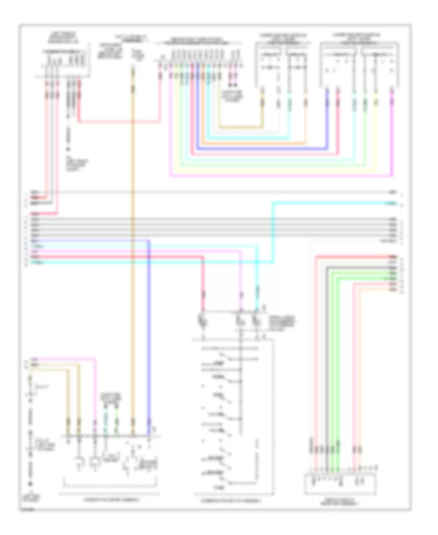
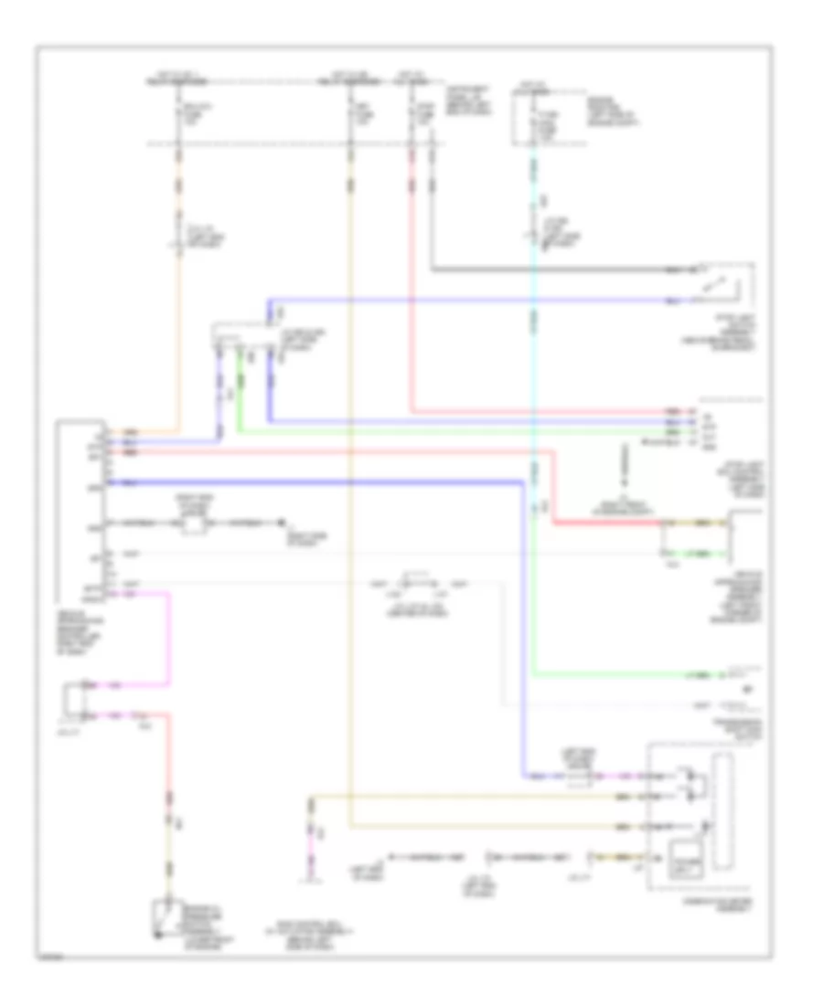
Navigation Wiring Diagram, with Radio & Display Receiver Type (1 of 3) for Toyota Prius V 2013

List of elements for Navigation Wiring Diagram, with Radio & Display Receiver Type (1 of 3) for Toyota Prius V 2013:
- (left side of liftgate) rear television camera
- (top of parking brake pedal assembly) parking brake switch
- A16
- A37
- A50
- Adpg
- Agnd
- Al2
- Al4
- B16
- C18
- C20
- C31
- Ca+
- Ca1h
- Ca1l
- Can h
- Can l
- Cb+
- Cgnd
- Computer data lines system
- Cv+
- Cv-
- Ecu-acc fuse 10a
- Ecu-b fuse 7.5a
- Ecu-ig2 fuse 10a
- Engine room r/b (left side of engine compt)
- Gauge fuse 10a
- Hot at all times
- Hot w/ acc relay energized
- Hot w/ ig1 1 relay energized
- Instrument panel j/b (behind left end of dash)
- J/c l70 (left end of dash)
- J/c l85 (center of dash)
- L135
- L34
- L35
- Ll2
- Lr1
- Macc
- Main antenna
- Map light assembly
- Mco+
- Mco-
- Microphone & microphone amplifier
- Min+
- Min-
- Nca
- P/i 2 fuse 40a
- Pkb
- Pnk
- Rad 1 fuse 15a
- Radio & display receiver assembly
- Red
- Rev
- Sgnd
- Skid control ecu (w/ actuator assembly) (behind left side of dash)
- Sns 2
- Sns2
- Sp1
- Spd
- Stereo jack adapter assembly 1
- Sub antenna
- Sw1
- Sw2
- Swg
- Ul1
- Va-
- Val+
- Var+
- Vr1
- W/ extension module
- W/o extension module
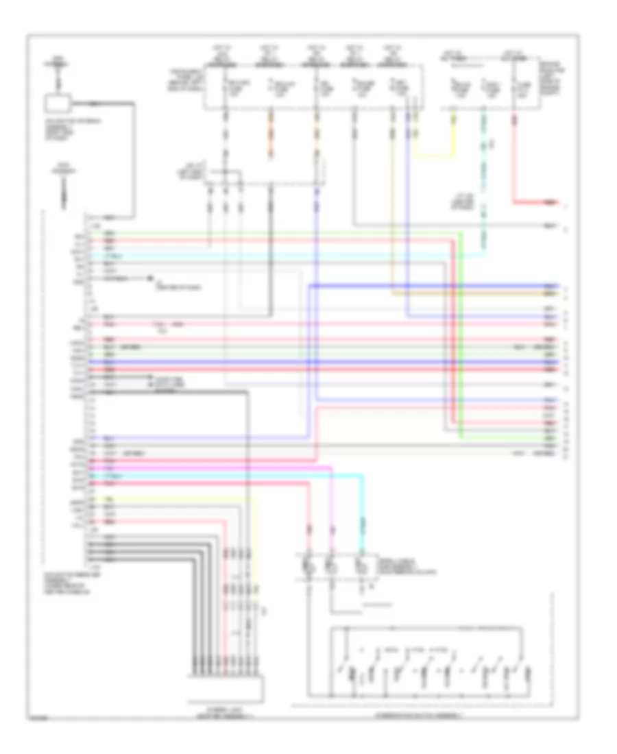
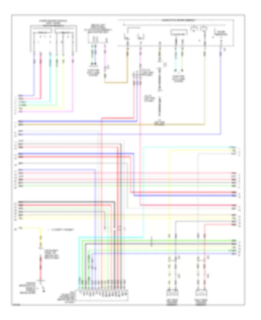
Navigation Wiring Diagram, with Radio & Display Receiver Type (2 of 3) for Toyota Prius V 2013
List of elements for Navigation Wiring Diagram, with Radio & Display Receiver Type (2 of 3) for Toyota Prius V 2013:
- (behind right side of dash) power management control ecu
- (left end of dash)
- (left side of engine compt) engine room j/b
- (under center console)
- (under center console) shift lever position sensor
- A21
- A3 (left front of engine compt)
- A44
- Au1
- Au2
- Avc+
- Avc-
- Batt
- Bkup
- Ca1h
- Ca1l
- Can driver
- Combination meter assembly
- Computer data lines system
- E2x1
- E2x2
- Eau
- G13
- G14
- G22
- Gnd1
- Gnd2
- Hall ic
- Hot w/ ig2 relay energized
- I/f
- Ig1
- Instrument panel j/b (behind left end of dash)
- Integration relay
- J/c l70
- J/c l71
- L27
- L3 (left end of dash)
- L52
- Met fuse 7.5a
- Mode
- Mute
- Nav
- Nca
- Off hook
- On hook
- Pnk
- Radio & display receiver assembly
- Red
- Seek+
- Seek-
- Shd3
- Shift lever position sensor 2
- Spiral cable sub-assembly (on steering column)
- Steering pad switch assembly
- Vcx1
- Vcx2
- Vcx3
- Vcx4
- Voice
- Volume+
- Volume-
- Vsx1
- Vsx2
- Vsx3
- Vsx4
- Z24
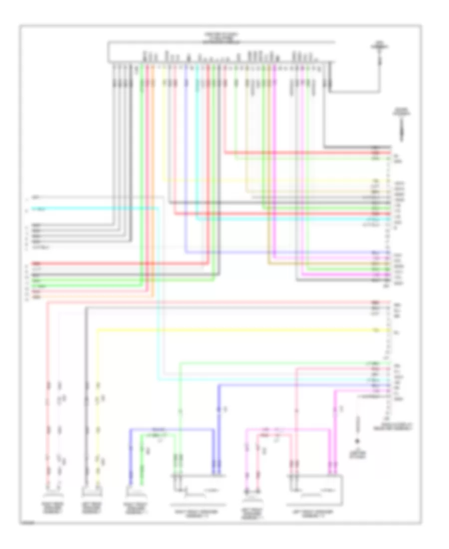
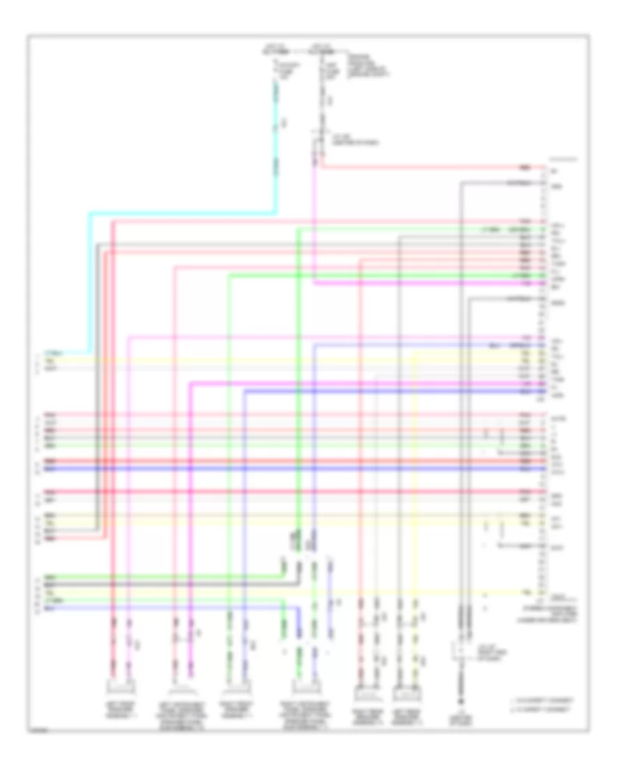
Navigation Wiring Diagram, with Radio & Display Receiver Type (3 of 3) for Toyota Prius V 2013
List of elements for Navigation Wiring Diagram, with Radio & Display Receiver Type (3 of 3) for Toyota Prius V 2013:
- (center of dash) (if equipped) extension module
- +b1
- Acc
- Acc1
- Agnd
- Avc+
- Avc-
- Fl+
- Fl-
- Fr+
- Fr-
- Gnd1
- Gps antenna
- Hsyn
- L11
- L140
- L2 (center of dash)
- L36
- L41
- Left front speaker assembly 1
- Left front speaker assembly 2
- Left rear speaker assembly
- Li1
- Lr1
- Ls1
- Mic+
- Mic-
- Mute
- Nca
- Nl2
- Ol2
- Pnk
- Ps1
- Qr1
- Radio & display receiver assembly
- Red
- Right front speaker assembly 1
- Right front speaker assembly 2
- Right rear speaker assembly
- Rl+
- Rl-
- Rr+
- Rr-
- Sdars antenna
- Shd1
- Shd2
- Shd3
- Spd
- V-b
- V-g
- V-r
- Vol+
- Vol-
- Vshd
- Vsyn
- Z22
- Z23
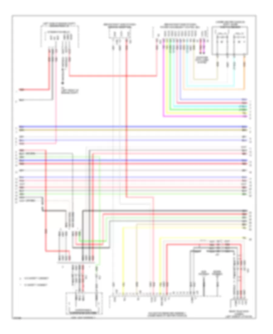
Navigation Wiring Diagram, without Radio & Display Receiver Type (1 of 4) for Toyota Prius V 2013
List of elements for Navigation Wiring Diagram, without Radio & Display Receiver Type (1 of 4) for Toyota Prius V 2013:
- (or red)
- A32
- A37
- A44
- A50
- Acc1
- Adpg
- Agnd
- Al2
- Al4
- Au1
- Au2
- B1+
- B16
- C18
- C31
- Canh
- Canl
- Computer data lines system
- Eau
- Ecu-acc fuse 10a
- Ecu-b fuse 7.5a
- Ecu-ig 2 fuse 10a
- Engine room r/b (left side of engine compt)
- Fl+
- Fl-
- Fr+
- Fr-
- Fuse p/i 2 40a
- Gauge fuse 10a
- Gnd
- Gps antenna
- Hot at all times
- Hot w/ acc relay energized
- Hot w/ ig1 1 relay energized
- Hot w/ ig2 relay energized
- Ign fuse 10a
- Instrument panel j/b (behind left end of dash)
- J/b l70 (left end of dash)
- J/c l85 (center of dash)
- L134
- L138
- L2 (center of dash)
- L38
- L39
- Ll2
- Macc
- Main antenna
- Met fuse 7.5a
- Min+
- Min-
- Mode
- Mut2
- Navigation antenna assembly (right end of dash)
- Navigation receiver assembly (under rear of center console)
- Nca
- Off hook
- On hook
- Pnk
- Rad 1 fuse 15a
- Red
- Rev
- Seek+
- Seek-
- Sgnd
- Sns2
- Spd
- Spiral cable sub-assembly (on steering column)
- Steering pad switch assembly
- Stereo jack adapter assembly 1
- Sw1
- Sw2
- Swg
- Tx1+
- Tx1-
- Va-
- Val+
- Var+
- Voice
- Volume+
- Volume-
Navigation Wiring Diagram, without Radio & Display Receiver Type (2 of 4) for Toyota Prius V 2013
List of elements for Navigation Wiring Diagram, without Radio & Display Receiver Type (2 of 4) for Toyota Prius V 2013:
- (behind right side of dash) parking assist ecu
- (behind right side of dash) power management control ecu
- (left side of engine compt) engine room j/b
- (or red)
- (under center console) shift lever position sensor
- A21
- A3 (left front of engine compt)
- Bat
- Bkup
- Brk sw
- Ca+
- Ca1h
- Ca1l
- Cb+
- Cgnd
- Computer data lines system
- Cv+
- Cv-
- E2x1
- E2x2
- G13
- G14
- G22
- Gnd1
- Gnd2
- Gvif
- Hall ic
- Ig1
- Integration relay
- L136
- L137
- L37
- L40
- L64
- Lr1
- Macc
- Map light assembly
- Mco+
- Mco-
- Microphone & microphone amplifier
- Nav
- Navigation receiver assembly (under rear of center console)
- Nca
- Pnk
- Rear television camera (left side of liftgate)
- Red
- Rl+
- Rl-
- Sdars antenna
- Sns2
- Sub antenna
- Tx3+
- Tx3-
- Txt+
- Txt-
- Ul1
- Vcx1
- Vcx2
- Vcx3
- Vcx4
- Vr1
- Vsx1
- Vsx2
- Vsx3
- Vsx4
- W/ safety connect
- W/o safety connect
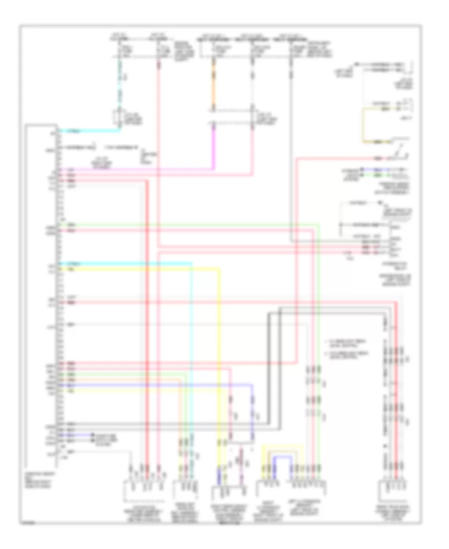
Navigation Wiring Diagram, without Radio & Display Receiver Type (3 of 4) for Toyota Prius V 2013
List of elements for Navigation Wiring Diagram, without Radio & Display Receiver Type (3 of 4) for Toyota Prius V 2013:
- (behind left side of dash) (w/ actuator assembly) skid control ecu
- (under center console) shift lever position sensor 2
- A16
- Acc
- Al2
- C20
- Ca1h
- Ca1l
- Can driver
- Canh
- Canl
- Combination meter assembly
- Computer data lines system
- Dcm (telematics transceiver) (behind center of dash)
- Hall ic
- I/f
- Ig+
- Ig2
- Instrument panel j/b (behind left end of dash)
- J/c l70 (left end of dash)
- J/c l71
- L27
- L3 (left end of dash)
- Left rear speaker assembly
- Li1
- Lr1
- Ls1
- Mci+
- Mci-
- Mco+
- Mco-
- Mcvd
- Mute
- Nca
- Parking brake switch (base of parking brake lever)
- Pnk
- Ps1
- Qr1
- Red
- Right rear speaker assembly
- Sgnd
- Sp1
- Spdp
- Spi+
- Spi-
- Spo+
- Spo-
- W/ safety connect
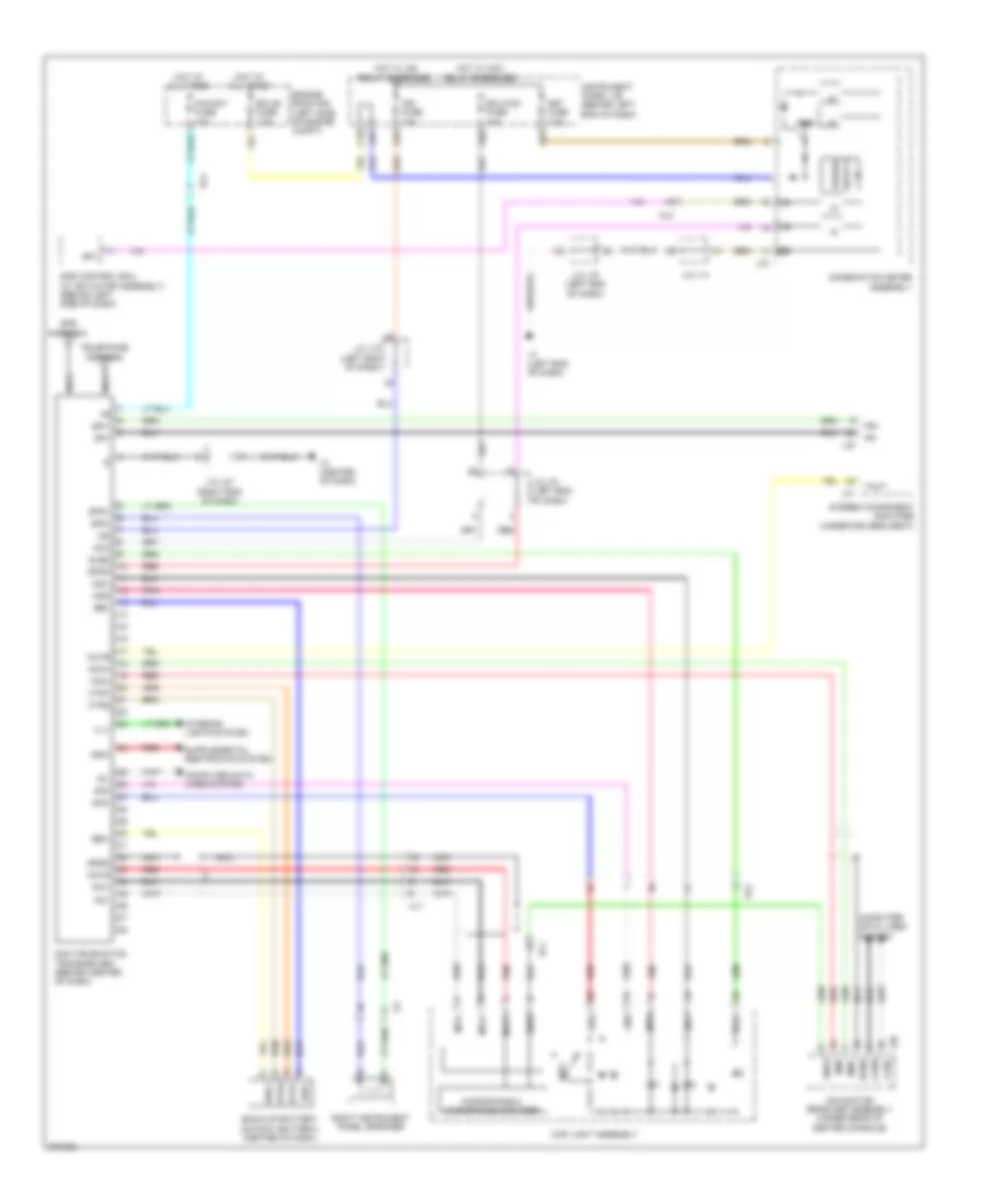
Navigation Wiring Diagram, without Radio & Display Receiver Type (4 of 4) for Toyota Prius V 2013
List of elements for Navigation Wiring Diagram, without Radio & Display Receiver Type (4 of 4) for Toyota Prius V 2013:
- Acc
- Al4
- Amp fuse 30a
- Atx+
- Atx-
- B2+
- Engine room r/b (left side of engine compt)
- Fl+
- Fl-
- Fr+
- Fr-
- Gnd
- Gnd2
- Hot at all times
- Int+
- Int-
- J/c l85 (center of dash)
- J/c l87 (right end of dash)
- L2 (center of dash)
- L30
- L31
- Left front speaker assembly 1
- Left instrument panel speaker (instrument panel speaker panel sub-assembly 2)
- Left rear speaker assembly 2
- Li1
- Lr1
- Ls1
- Mayday fuse 10a
- Mute
- Nca
- Nl2
- Ol2
- Pnk
- Ps1
- Qr1
- Red
- Right front speaker assembly 1
- Right instrument panel speaker (instrument panel speaker panel sub-assembly 1)
- Right rear speaker assembly 2
- Rl+
- Rl-
- Rr+
- Rr-
- Sld
- Sld1
- Spd
- Stereo component amplifier (under driver's seat)
- Tmut
- Twl+
- Twl-
- Twr+
- Twr-
- W/ safety connect
- W/o safety connect
- Wfl+
- Wfl-
- Wfr+
- Wfr-
Parking Assistant Wiring Diagram for Toyota Prius V 2013
List of elements for Parking Assistant Wiring Diagram for Toyota Prius V 2013:
- A3 (left front of engine compt)
- A50
- Acc
- Al1
- Al2
- Al4
- Al7
- Al8
- As1
- B16
- Batt
- C31
- Ca1
- Canh
- Canl
- Cb+
- Cgnd
- Computer data lines system
- Csb3
- Csg3
- Cv+
- Cv-
- Ecu-acc fuse 10a
- Ecu-ig 2 fuse 10a
- Engine room j/b (left side of engine compt)
- Engine room r/b (left side of engine compt)
- G14
- G22
- Gauge fuse 10a
- Gnd1
- Gnd2
- Gvif
- Hb+
- Hbe+
- Hbl+
- Headlight leveling ecu assembly (behind right end of dash)
- Hg1
- Hgnd
- Hl1
- Ho1
- Hot at all times
- Hot w/ acc relay energized
- Hot w/ ig1 1 relay energized
- Ig1
- Instrument panel j/b (behind left end of dash)
- Integration relay
- Interior lights system
- Issw
- J/b l70 (left end of dash)
- J/b l71
- J/c l70 (left end of dash)
- J/c l85 (center of dash)
- J/c l87 (right end of dash)
- L136
- L137
- L2 (center of dash)
- L3 (left end of dash)
- L37
- L38
- L64
- L65
- Left ultrasonic sensor 1 (left front of engine compt)
- Level control
- Lin 3
- Lr1
- Ls1
- Nav
- Navigation receiver assembly (under rear of center console)
- Nca
- P/i 2 fuse 40a
- Parking assist ecu (behind right side of dash)
- Parking assist pre support switch assembly
- Pnk
- Rad 1 fuse 15a
- Rear television camera assembly (left side of liftgate)
- Red
- Rev
- Right rear height control sensor sub-assembly (right side of rear axle)
- Right ultrasonic sensor 1 (right front of engine compt)
- Sbr
- Sgr
- Shb
- Shg
- Shrl
- Shrr
- Tx+
- Tx-
- Tx3+
- Tx3-
- Vr1
- W/ headlight beam
- W/o headlight beam
Telematics Wiring Diagram for Toyota Prius V 2013
List of elements for Telematics Wiring Diagram for Toyota Prius V 2013:
- A32
- A37
- A44
- A50
- Acc
- Al2
- Al4
- Back-up battery (mayday battery) (center of dash)
- Bbi+
- Bbi-
- Bbo+
- Bbo-
- Btr1
- Btr2
- C18
- Canh
- Canl
- Combination meter assembly
- Computer data lines system
- Ctr1
- Ctr2
- Dcm (telematics transceiver) (behind center of dash)
- Ecu-acc fuse 10a
- Ecu-b fuse 7.5a
- Engine room r/b (left side of engine compt)
- Fr+
- Fr-
- Gnd
- Gps antenna
- Gsw
- Hot at all times
- Hot w/ acc relay energized
- Hot w/ ig2 relay energized
- I/f
- Ig2
- Ign fuse 10a
- Ign2
- Ill+
- Ind1
- Ind2
- Instrument panel j/b (behind left end of dash)
- Interior lights system
- J/c l70 (left end of dash)
- J/c l71
- J/c l87 (right end of dash)
- L2 (center of dash)
- L27
- L3 (left end of dash)
- L30
- L31
- L38
- Li1
- Macc
- Map light assembly
- Mayday fuse 10a
- Mci+
- Mci-
- Mco+
- Mco-
- Mcvd
- Met fuse 7.5a
- Microphone & microphone amplifier
- Min+
- Min-
- Mute
- Navigation receiver assembly (under rear of center console)
- Nca
- Pnk
- Power
- Red
- Right instrument panel speaker
- Rrid
- Sgnd
- Sig-
- Sig1
- Sig2
- Sil
- Skid control ecu (w/ actuator assembly) (behind left side of dash)
- Sled
- Sns2
- Sos
- Sp1
- Spdp
- Spi+
- Spi-
- Spo+
- Spo-
- Stereo component amplifier (under driver's seat)
- Telephone antenna
- Tmut
- Ul1
- Ul2
Vehicle Proximity Notification Wiring Diagram for Toyota Prius V 2013
List of elements for Vehicle Proximity Notification Wiring Diagram for Toyota Prius V 2013:
- (left end of dash) j/c l70
- (right end of dash) j/c l93
- A1 (right front of engine compt)
- A44
- A50
- A52
- A53
- Al2
- Al4
- B16
- C11
- C12
- Combination meter assembly
- Da1
- Ecu-ig 2 fuse 10a
- Engine oil pressure switch assembly (lower front of engine)
- Engine room r/b (left side of engine compt)
- Gnd
- Hot at all times
- Hot w/ ig1 1 relay energized
- Hot w/ ig2 relay energized
- I/f
- Ig+
- Instrument panel j/b (behind left end of dash)
- J/c a50 & a52 (left side of dash) a52
- J/c a52 & a53 (left side a52 of dash)
- J/c l101 & l102 (center of dash)
- J/c l70 (left end of dash)
- J/c l71
- L1 (right side of dash)
- L101
- L102
- L27
- L3 (left end of dash)
- Met fuse 10a
- Opsw
- Out
- P con main fuse 7.5a
- Power sply
- Red
- Sftp
- Skid control ecu (w/ actuator assembly) (behind left side of dash)
- Sp+
- Sp-
- Spd
- Stop fuse 10a
- Stop light ecu control assembly (left side of dash)
- Stop light switch assembly (above brake pedal, on bracket)
- Stp
- Transmission shift main switch
- Vehicle approaching speaker assembly (left front corner of engine compt)
- Vehicle approaching speaker controller (right end of dash)