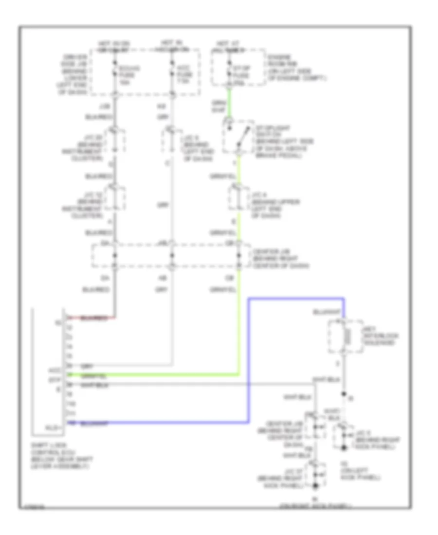
SHIFT INTERLOCK
Shift Interlock Wiring Diagram for Toyota 4Runner SR5 2003
List of elements for Shift Interlock Wiring Diagram for Toyota 4Runner SR5 2003:
- Acc
- Acc fuse 7.5a
- Center j/b (behind right center of dash)
- Driver side j/b (behind lower left end of dash)
- Ecu-ig fuse 10a
- Engine room r/b (on left side of engine compt)
- Hot at all times
- Hot in acc or on
- Hot in on or start
- Ig (on left kick panel)
- Ik (on right kick panel)
- J/c 12 (behind instrument cluster)
- J/c 20 (behind instrument cluster)
- J/c 37 (behind right kick panel)
- J/c 4 (behind upper left end of dash)
- J/c 5 (behind right kick panel)
- J/c 6 (behind left end of dash)
- J28
- Key interlock solenoid
- Kls+
- Shift lock control ecu (below gear shift lever assembly)
- Stop fuse 10a
- Stoplight switch (behind left side of dash, above brake pedal)
- Stp
 English