
SHIFT INTERLOCK
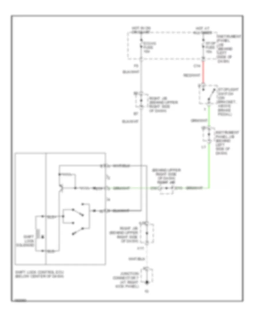
Shift Interlock Wiring Diagram for Toyota Matrix XR 2004
List of elements for Shift Interlock Wiring Diagram for Toyota Matrix XR 2004:
AIR CONDITIONINGANTI-LOCK BRAKESANTI-THEFTCOOLING FANBODY CONTROL MODULESEXTERIOR LIGHTSCRUISE CONTROLCOMPUTER DATA LINESHEADLIGHTSGROUND DISTRIBUTIONENGINE PERFORMANCEDEFOGGERSHORNINSTRUMENT CLUSTERINTERIOR LIGHTSPOWER DISTRIBUTIONPOWER MIRRORSRADIOPOWER TOP/SUNROOFPOWER DOOR LOCKSSUPPLEMENTAL RESTRAINTSPOWER WINDOWSSTARTING/CHARGINGSHIFT INTERLOCKTRANSMISSIONWARNING SYSTEMSWIPER/WASHER