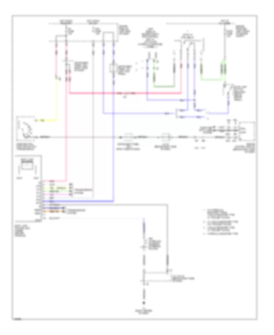
SHIFT INTERLOCK
Shift Interlock Wiring Diagram for Toyota Tacoma PreRunner 2014
List of elements for Shift Interlock Wiring Diagram for Toyota Tacoma PreRunner 2014:
- (left rear of engine compt) skid control ecu w/ actuator (hydraulic booster type)
- 2.7l
- 4.0l
- Acc
- Acc fuse 7.5a
- At2
- At3
- Atd
- Atl
- B13
- Canh
- Canl
- Computer data lines system
- Driver side j/b (left end of dash)
- E10
- E14
- E19
- E22
- Engine control module (behind right side of dash)
- Engine room r/b (left front of engine compt)
- H13
- Hot at all times
- Hot in run or acc
- Hot in run or start
- Hydraulic booster type
- Ia3
- Ic (right center of dash)
- Ig1 fuse 10a
- Ih1
- Ih2
- Instrument panel j/b 1 (left kick panel)
- Instrument panel j/b 2 (right side of dash)
- J/c j4 & j5 (behind right side of dash)
- J/c j5 (behind right side of dash)
- J10
- Key interlock solenoid (steering column)
- Kls+
- Nssd
- Nssl
- Park/neutral position switch (transmission)
- Pnk
- Shift lock control ecu (under center console)
- Shift lock solenoid
- Sls+
- Sls-
- Stop fuse 10a
- Stop lamp switch (bracket, above brake pedal)
- Stop lp ctrl relay
- Stp
- Stp2
- Stpo
- System
- Transmissions
- Vacuum booster type w/ trailer towing
- W/ hydraulic booster type & vacuum booster type w/ trailer towing
- W/ vacuum booster type w/o trailer towing
 English