
SHIFT INTERLOCKS
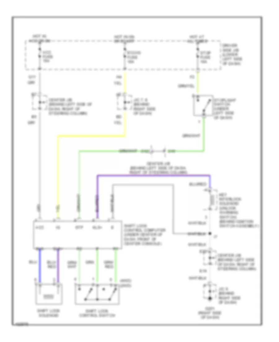
Shift Interlock Wiring Diagram for Toyota 4Runner SR5 1999
List of elements for Shift Interlock Wiring Diagram for Toyota 4Runner SR5 1999:
ANTI-LOCK BRAKESCOMPUTER DATA LINESCRUISE CONTROLDEFOGGERSAIR CONDITIONINGENGINE PERFORMANCEANTI-THEFTHEADLIGHTSEXTERIOR LIGHTSPOWER ANTENNAGROUND DISTRIBUTIONINSTRUMENT CLUSTERHORNPOWER DISTRIBUTIONPOWER MIRRORSPOWER DOOR LOCKSINTERIOR LIGHTSPOWER SEATSPOWER WINDOWSPOWER TOP/SUNROOFSTARTING/CHARGINGSUPPLEMENTAL RESTRAINTSRADIOSHIFT INTERLOCKSTRANSMISSIONWARNING SYSTEMSWIPER/WASHER