
SUPPLEMENTAL RESTRAINTS
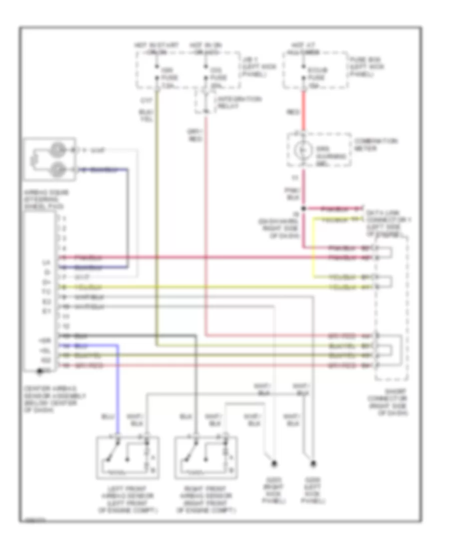
Supplemental Restraint Wiring Diagram for Toyota T100 SR5 1998
List of elements for Supplemental Restraint Wiring Diagram for Toyota T100 SR5 1998:
AIR CONDITIONINGCOMPUTER DATA LINESEXTERIOR LIGHTSCRUISE CONTROLANTI-LOCK BRAKESENGINE PERFORMANCEGROUND DISTRIBUTIONHORNPOWER DISTRIBUTIONINTERIOR LIGHTSINSTRUMENT CLUSTERHEADLIGHTSPOWER MIRRORSPOWER DOOR LOCKSRADIOWARNING SYSTEMSPOWER WINDOWSSUPPLEMENTAL RESTRAINTSTRANSMISSIONSTARTING/CHARGINGWIPER/WASHER