TRANSMISSION
Center Differential Lock Wiring Diagram for Toyota Land Cruiser 1995

List of elements for Center Differential Lock Wiring Diagram for Toyota Land Cruiser 1995:
- (engine harness, center of safety wall)
- (engine harness, left rear of eng.)
- (i/p harness, left side of dash)
- (i/p harness, right side of dash)
- A/t indicator switch (left side of trans)
- Anti- lock brakes system
- Center differential lock control motor (top of t-case)
- Center differential lock control relay (above left kick panel)
- Center differential lock indicator
- Center differential lock indicator switch (on t-case)
- Conn d
- Diff fuse 30a
- E18
- E22
- Engine control module (right side of dash)
- Fuse block (left side of dash)
- G114 (on air intake chamber)
- Gauge fuse 10a
- Hot in on or start
- I11
- Instrument cluster
- J/c 1 (left side of dash)
- J/c 2 (left side of dash)
- J/c 4 (left dash)
- Short pin (center of dash)
- Tfn
- Transfer l4 position switch (rear of trans)
- Transfer neutral position indicator
- Transfer neutral position switch (rear of trans)
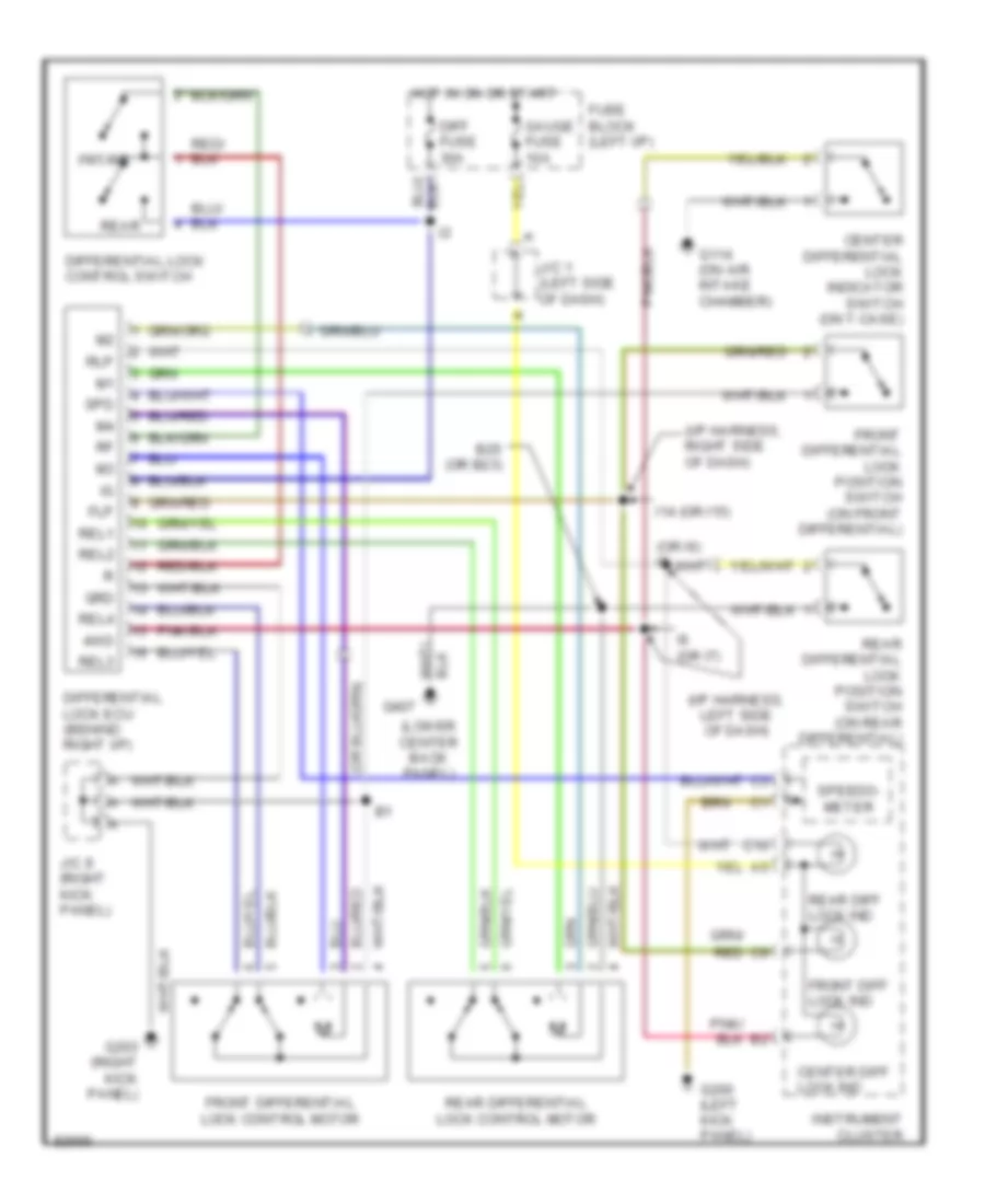
Front/Rear Differential Lock Wiring Diagram for Toyota Land Cruiser 1995
List of elements for Front/Rear Differential Lock Wiring Diagram for Toyota Land Cruiser 1995:
- rear differential lock position switch (on rear differential)
- (i/p harness, left side of dash)
- (i/p harness, right side of dash)
- (lower center back panel)
- (or i6) i5
- 4wd
- B25 (or b23)
- C10
- Center diff lock ind
- Center differential lock indicator switch (on t-case)
- Diff fuse 30a
- Differential lock control switch
- Differential lock ecu (behind right i/p)
- Flp
- Front diff lock ind
- Front differential lock control motor
- Front differential lock position switch (on front differential)
- Frt/rr
- Fuse block (left i/p)
- G114 (on air intake chamber)
- G200 (left kick panel)
- G203 (right kick panel)
- G407
- Gauge fuse 10a
- Grd
- Hot in on or start
- I14 (or i15)
- I6 (or i7)
- Instrument cluster
- J/c 1 (left side of dash)
- J/c 8 (right kick panel)
- Rear
- Rear diff lock ind
- Rear differential lock control motor
- Red
- Rel1
- Rel2
- Rel3
- Rel4
- Rlp
- Spd
- Speedo- meter
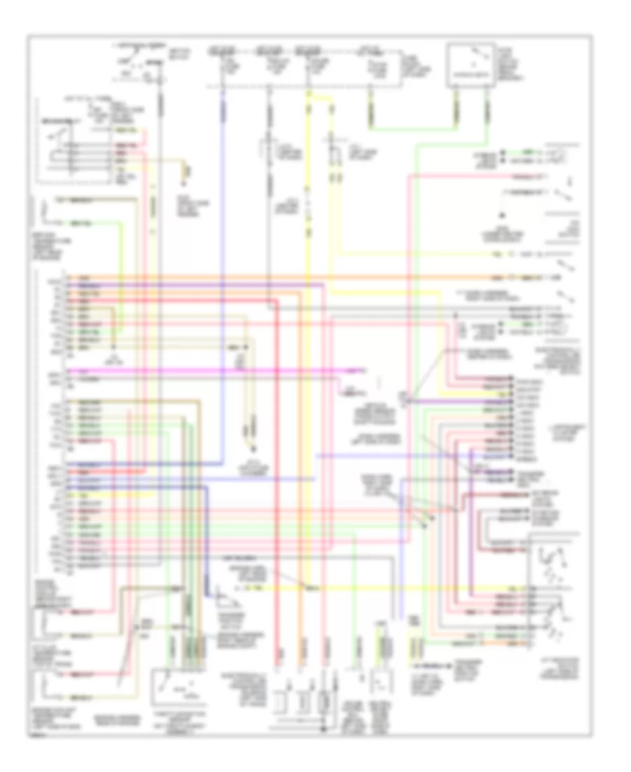
Transmission Wiring Diagram for Toyota Land Cruiser 1995
List of elements for Transmission Wiring Diagram for Toyota Land Cruiser 1995:
- (dash harn, right side of dash) i12 (or i13)
- (dash harness, center of dash)
- (dash harness, left side of dash)
- (dash harness, right side of dash)
- (engine harn, left rear of engine)
- (engine harness, rear of engine)
- (engine harness, right rear of engine compt)
- (or i10)
- (or i7) i6
- 1995,
- 2 indic
- 2nd
- 2nd strt
- A/t fluid temperature sensor (top of trans)
- A/t indicator switch (left side of transmission)
- Acc
- Cruise control ecu (behind left side of dash)
- D indic
- E16
- E18
- Ecu-ig fuse 15a
- Efi fuse 15a
- Efi main relay
- Egr gas temperature sensor (left rear of engine)
- Electronically controlled transmission pattern select switch
- Electronically controlled transmission solenoid (left side of trans)
- Engine control module (behind right side of dash)
- Engine coolant temperature sensor (left side of eng)
- Eo1
- Eo2
- Eo3
- Exterior lights system
- Fuse block (left side of dash)
- G100 (front side of left fender)
- G114 (air intake chamber)
- G302 (under center console box)
- Gauge fuse 10a
- Hold
- Hot at all times
- Hot in on or start
- I11 (or i12) (dash harn, right side of dash)
- I12 (or i13)
- I18 (or i19)
- Idl
- Ign fuse 75a
- Ignition switch
- Igsw
- Instrument cluster system
- Interior lights system
- J/c 1 (left side of dash)
- J/c 4 (center of dash)
- J/c 6 (center of dash)
- L indic
- Mrly
- N indic
- Neutral detect diode (right side of dash)
- No 1
- No 2
- No 3
- O/d indic
- O/d main switch
- Od1
- Od2
- Off
- P indic
- Pwr
- Pwr indic
- R indic
- R/b 2 (front side of left fender)
- Red
- Sp2+
- Sp2-
- Spd
- Speedo
- St1
- Start
- Starting/ charging system
- Stop fuse 10aa
- Stop light switch (brake pedal bracket)
- Stp
- Tfn
- Thg
- Throttle position sensor (on throttle body assembly)
- Thw
- Transfer neutral indic
- Transfer neutral position switch
- Transfer position switch
- Vcc
- Vehicle speed sensor (trans output shaft housing)
- Vta