TRANSMISSION
4.7L
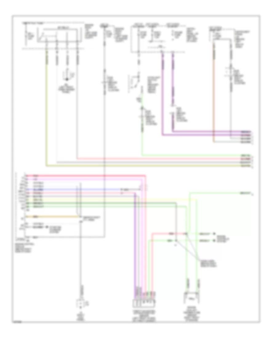
4.7L, 4WD Wiring Diagram for Toyota Sequoia Limited 2005

List of elements for 4.7L, 4WD Wiring Diagram for Toyota Sequoia Limited 2005:
- 2-4
- 4hi
- 4lo
- 4wd
- 4wd control ecu (behind lower right end of dash)
- 4wd fuse 20a
- A15
- A18
- Add
- Add actuator (on rear of engine)
- C/c
- Ccc
- Center diff lock
- Cluster)
- Combination meter
- Cpu
- Csw
- Dl1
- Dl2
- Dm1
- Dm2
- Engine control module (behind right side of dash)
- Ex12
- F10
- Gauge fuse 15a
- Gnd
- H11
- Hl1
- Hl2
- Hm1
- Hm2
- Hot in on or start
- Hot in run or acc
- Hot in run or start
- I19
- I22
- Ie (left kick panel)
- Ig (right kick panel)
- Ign1 fuse 10a
- Ind1
- Ind2
- Ind3
- Instrument panel j/b (behind left end of dash)
- Integration control & panel (behind center of dash)
- Io (right dash brace)
- Ipo
- J/c 41 (right side of dash)
- J/c j51 & j52 (behind j51
- J17 (behind left center of dash)
- J18
- J43 (right side of dash)
- J51
- J51 e
- J52
- J52 b
- Park/ neutral position switch (on trans)
- Pnk
- Rad 2 fuse 7.5a
- Red
- Right end of dash)
- Spd
- Speedo
- Sub j/b 3 (behind right side of instrument cluster)
- Sub j/b 4 (behind right side of inst a17
- Tl1
- Tl2
- Tl3
- Tm1
- Tm2
- Transfer shift actuator (on trans- mission)
- Translate ecu (above right kick panel)
- Vehicle speed sensor (on trans)
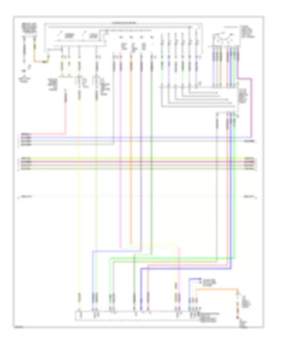
4.7L, A/T Wiring Diagram (1 of 3) for Toyota Sequoia Limited 2005
List of elements for 4.7L, A/T Wiring Diagram (1 of 3) for Toyota Sequoia Limited 2005:
- (dash harn, behind right side of dash)
- (rear of right cyl head)
- A15
- A19
- E01
- E02
- E17
- Ed (left front inner fender panel)
- Efi 1 fuse 20a
- Efi relay
- Engine control module (behind right side of dash)
- Engine controls system
- Engine coolant temperature sensor (right front of engine)
- Engine room j/b (left side of engine compt)
- Engine room r/b 2 (left side of engine compt)
- Gauge fuse 10a
- Geo1
- H11
- Hot at all times
- Hot in run or acc
- Hot in run or start
- Hot in start
- Ig (right kick panel)
- Ign 1 fuse 10a
- Instru- ment panel j/b (behind left end of dash)
- Instrument panel j/b (behind left end of dash)
- Ipo
- J/c j18
- J/c j5
- Nca
- Pnk
- Pnk m+
- Rad 2 fuse 7.5a
- Red
- Red vc
- Sta
- Sta fuse 7.5a
- Starting/ charging system
- Stop fuse 15a
- Stoplight switch (on bracket, above brake pedal)
- Stsw
- Sub j/b 3 (behind right side of cluster)
- Sub j/b 4 (behind right side of cluster)
- Throttle control motor & position sensor (left front of eng, on throttle body)
- Thw
- Vta1
- Vta2
4.7L, A/T Wiring Diagram (2 of 3) for Toyota Sequoia Limited 2005
List of elements for 4.7L, A/T Wiring Diagram (2 of 3) for Toyota Sequoia Limited 2005:
- (4wd)
- (behind left end of dash) instrument panel j/b
- A/t oil temp ind
- Canh
- Canl
- Combination meter
- Computer data lines system
- Engine control module (behind right side of dash)
- Eom
- Ie (left kick panel)
- Ig (right kick panel)
- J/c j14 & jc15
- J/c j17 (behind left center of dash)
- J/c j43 (right side of dash)
- J/c j51 j& j52 (behind right end of dash)
- J/c j8
- J51
- J52
- Llp
- Malf ind lamp
- O/d off ind
- Odlp
- Oilw
- Park/ neutral position switch (on trans)
- Spd
- Speedo- meter
- Tach
- Tacho- meter
- Vehicle speed sensor (on trans)
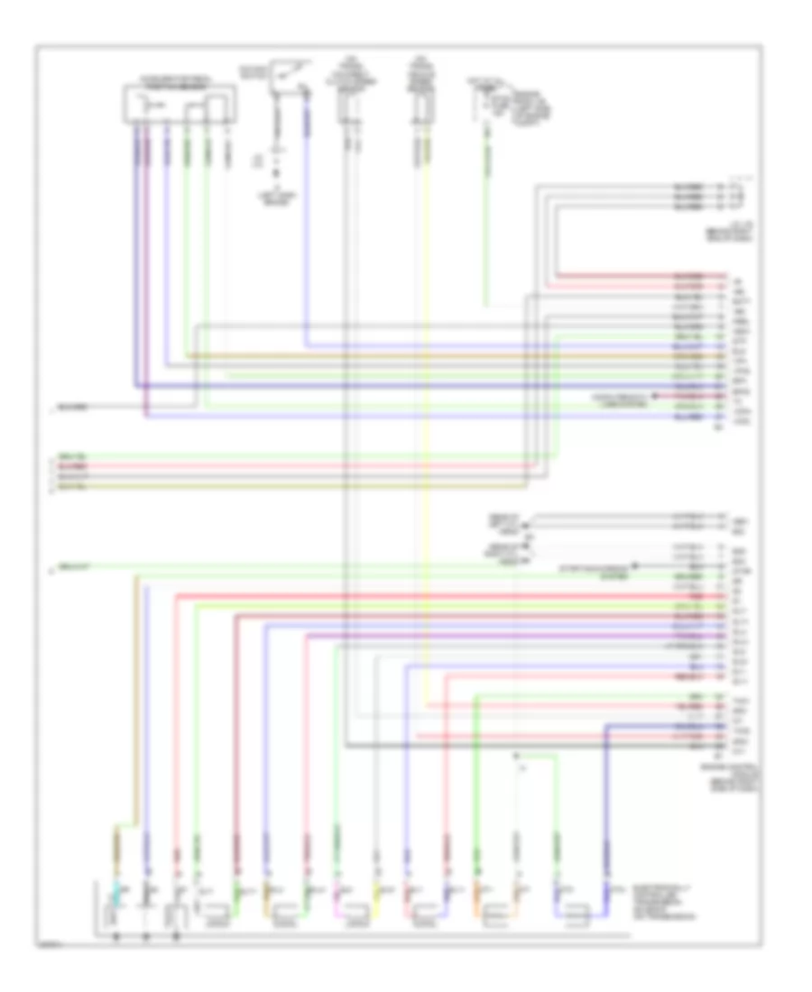
4.7L, A/T Wiring Diagram (3 of 3) for Toyota Sequoia Limited 2005
List of elements for 4.7L, A/T Wiring Diagram (3 of 3) for Toyota Sequoia Limited 2005:
- (on trans) o/d direct clutch speed sensor
- (on trans) vehicle speed sensor
- (rear of left cyl head)
- (rear of right cyl head)
- +b2
- +bm
- Accelerator pedal position sensor
- Batt
- Computer data lines system
- E03
- Electronically controlled transmission solenoid (on transmission)
- Els
- Engine control module (behind right side of dash)
- Engine room j/b (left side of engine compt)
- Eo4
- Eo5
- Epa
- Epa2
- Etcs fuse 15a
- Hot at all times
- If (left dash brace)
- Igsw
- J/c j12
- J/c j16 (behind right eng of dash)
- Me01
- Mrel
- Nt+
- Nt-
- O/d main switch
- Ot+
- Ot-
- Ot2+
- Ot2-
- Red
- Sl1+
- Sl1-
- Sl2+
- Sl2-
- Slt+
- Slt-
- Slu+
- Slu-
- Sp2+
- Sp2-
- Star
- Starting/charging system
- Stp
- Tho1
- Tho2
- Vcp2
- Vcpa
- Vpa
- Vpa2