TRANSMISSION
2.7L
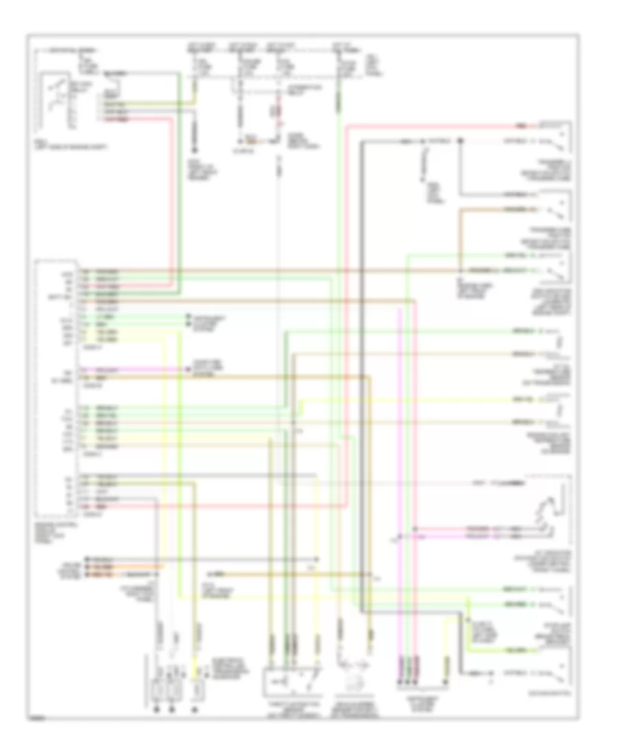
2.7L, Transmission Wiring Diagram for Toyota T100 1995

List of elements for 2.7L, Transmission Wiring Diagram for Toyota T100 1995:
- (1996 only)
- A/t indicator (p/n position) switch (under central trans tunnel)
- A/t oil temperature sensor (on transmission)
- Batt (b+)
- C17
- Cig fuse 15a
- Computer data lines system
- Conn a
- Conn b
- Conn c
- Conn d
- Cruise control system
- Diode (behind right dash)
- E1 (grd)
- Efi fuse 15a
- Efi main
- Electronic controlled transmission solenoids
- Engine control module (right kick panel)
- Engine coolant temperature sensor (on engine)
- G100 (front of left front fender)
- G110 (left front of engine)
- G200 (left kick panel)
- Gauge fuse 10a
- Hot at all times
- Hot in acc or run
- Hot in run or start
- I12
- I12 (i/p harn, right kick panel)
- I14
- I14 (i/p harn, right kick panel)
- I4 (i/p harness, left side of dash)
- Idl
- Ign fuse 7.5a
- Instrument cluster system
- Integration relay
- J/b 1 (left kick panel)
- Nca
- No. 1
- No. 2
- No. 3
- O/d main switch
- Od2
- Oil
- R/b 2 (left side of engine compt)
- Red
- Relay
- Sp1
- Sp2+
- Sp2-
- Stop fuse 10a
- Stoplamp switch (brake pedal bracket)
- Te1
- Throttle position sensor (on throttle body)
- Thw
- Vcc
- Vehicle speed sensor (for ect) (on transmission)
- Vta
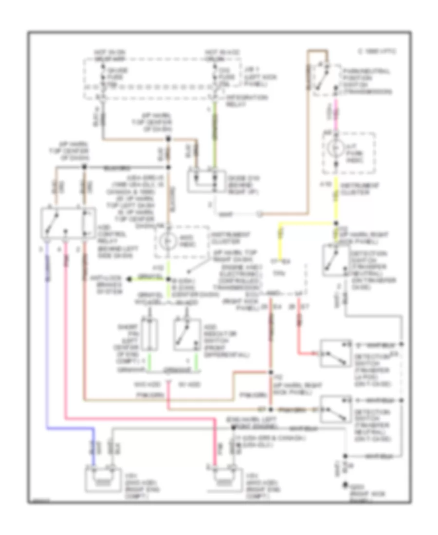
Transfer Case Wiring Diagram, A/T for Toyota T100 1995
List of elements for Transfer Case Wiring Diagram, A/T for Toyota T100 1995:
- (behind left side dash)
- (eng harn, left front engine)
- (i/p harn, right kick panel)
- (i/p harn, top center of dash)
- (i/p harn, top right dash)
- (left kick panel)
- (usa-sr5) i5 (1995 usa-dlx, i6
- 4wd
- 4wd indic.
- A/t park indic.
- A10
- A12
- Add control relay
- Add indicator switch (front differential)
- Anti-lock brakes system
- C 1995 vftc
- Canada & 1996) (i5: i/p harn, top left dash i6: i/p harn, top center dash)
- Cig fuse 15a
- Detection switch (transfer l4 pos) (on t-case)
- Detection switch (transfer neutral) (on t-case)
- Detection switch (transfer neutral) (on transfer case)
- Diode d10 (behind right i/p)
- Engine and electronic controlled transmission ecu (right kick panel)
- G203 (right kick panel)
- Gauge fuse 10a
- Hot in acc or on
- Hot in on or start
- I1 (usa-sr5 & canada) i6 (usa-dlx)
- I12
- I9 (usa) i6 (can) (center dash)
- Instrument cluster
- Integration relay
- J/b 1
- Park/neutral position switch (transmission)
- Pnk
- Red
- Short pin (left center of eng compt)
- Tfn
- Vsv (2wd add) (right eng compt)
- Vsv (4wd add) (right eng compt)
- W/ add
- W/o add
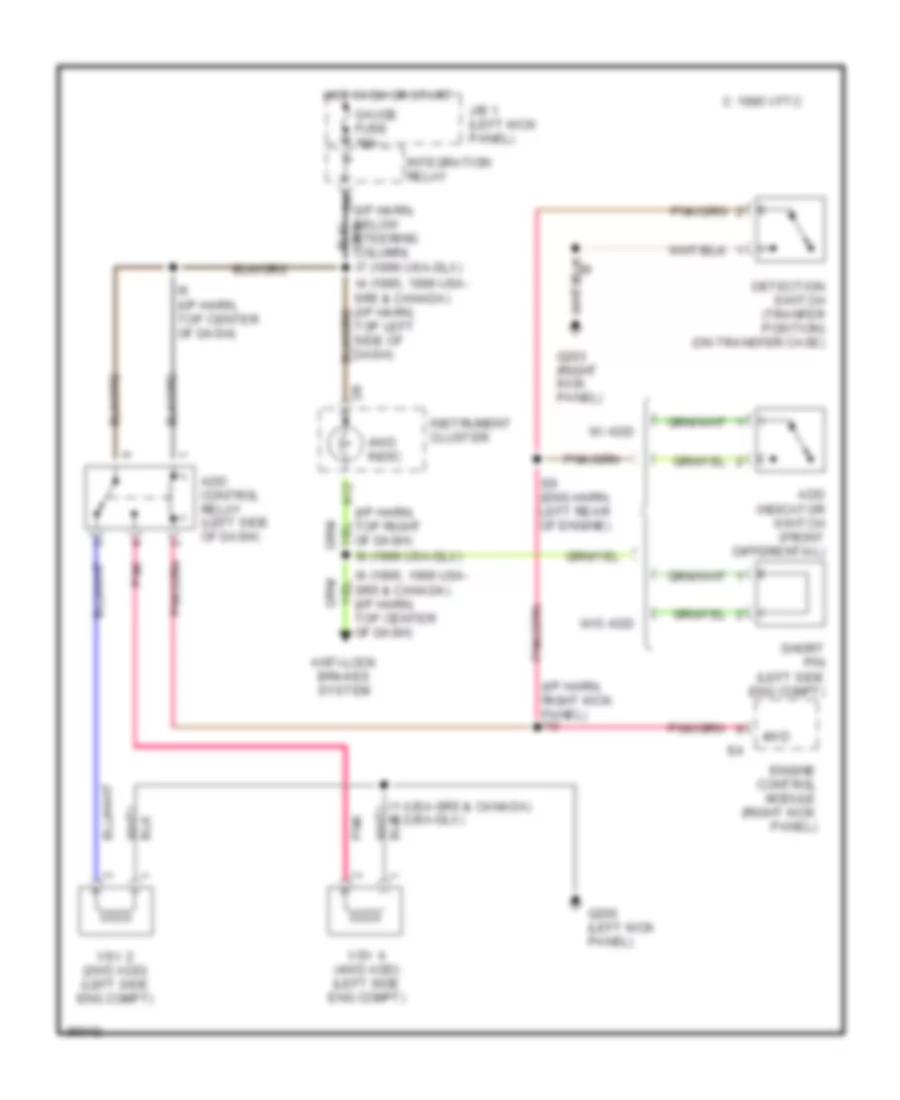
Transfer Case Wiring Diagram, M/T for Toyota T100 1995
List of elements for Transfer Case Wiring Diagram, M/T for Toyota T100 1995:
- (i/p harn, below steering column)
- (i/p harn, right kick panel) i12
- 4wd
- 4wd indic.
- A12
- Add control relay (left side of dash)
- Add indicator switch (front differential)
- Anti-lock brakes system
- C 1995 vftc
- Detection switch (tranfer position) (on transfer case)
- E8 (eng harn, left rear of engine)
- Engine control module (right kick panel)
- G200 (left kick panel)
- G203 (right kick panel)
- Gauge fuse 10a
- Hot in on or start
- I1 (usa-sr5 & canada) i6 (usa-dlx)
- I6 (1995, 1996 usa- sr5 & canada) (i/p harn, top center of dash)
- I6 (i/p harn, top center of dash)
- I7 (1996 usa-dlx)
- I9 (1996 usa-dlx)
- Instrument cluster
- Integration relay
- J/b 1 (left kick panel)
- Of dash)
- Pnk
- Short pin (left side eng compt)
- Top left side of dash)
- Vsv 2 (2wd add) (left side eng compt)
- Vsv 4 (4wd add) (left side eng compt)
- W/ add
- W/o add
3.4L
3.4L, Transmission Wiring Diagram for Toyota T100 1995
List of elements for 3.4L, Transmission Wiring Diagram for Toyota T100 1995:
- 4wd
- A/t indicator (p/n position) switch (under central trans tunnel)
- A/t oil temperature sensor (on transmission)
- Add indicator switch or add jumper pin (left rear of engine compt)
- Batt (b+)
- C17
- Cig fuse 15a
- Computer data lines system
- Conn a
- Conn b
- Conn c
- Conn d
- Cruise control system
- Diode (behind right dash)
- E1 (grd)
- E7 (engine harn, left front of engine)
- Efi fuse 15a
- Efi main
- Electronic controlled transmission solenoids
- Engine control module (right kick panel)
- Engine coolant temperature sensor (on engine)
- G100 (front of left front fender)
- G110 (left front of engine)
- G200 (left kick panel)
- Gauge fuse 10a
- Hot at all times
- Hot in acc or run
- Hot in run or start
- I14
- I14 (i/p harness, right kick panel)
- I5 (or i6)
- I5 (or i7) (i/p harn, left side of dash)
- Idl
- Ign fuse 7.5a
- Instrument cluster system
- Integration relay
- J/b 1 (left kick panel)
- Nca
- No. 1
- No. 2
- No. 3
- O/d main switch
- Od1
- Od2
- Oil
- Oilw
- R/b 2 (left side of engine compt)
- Red
- Relay
- Sp2
- Spd
- Stop fuse 10a
- Stoplamp switch (brake pedal bracket)
- Te1
- Throttle position sensor (on throttle body)
- Thw
- Transfer case position detection switch (transfer case)
- Transfer l4 position detection switch (transfer case)
- Vcc
- Vehicle speed sensor (for ect) (on transmission)
- Vta
Transfer Case Wiring Diagram, A/T for Toyota T100 1995
List of elements for Transfer Case Wiring Diagram, A/T for Toyota T100 1995:
- (behind left side dash)
- (eng harn, left front engine)
- (i/p harn, right kick panel)
- (i/p harn, top center of dash)
- (i/p harn, top right dash)
- (left kick panel)
- (usa-sr5) i5 (1995 usa-dlx, i6
- 4wd
- 4wd indic.
- A/t park indic.
- A10
- A12
- Add control relay
- Add indicator switch (front differential)
- Anti-lock brakes system
- C 1995 vftc
- Canada & 1996) (i5: i/p harn, top left dash i6: i/p harn, top center dash)
- Cig fuse 15a
- Detection switch (transfer l4 pos) (on t-case)
- Detection switch (transfer neutral) (on t-case)
- Detection switch (transfer neutral) (on transfer case)
- Diode d10 (behind right i/p)
- Engine and electronic controlled transmission ecu (right kick panel)
- G203 (right kick panel)
- Gauge fuse 10a
- Hot in acc or on
- Hot in on or start
- I1 (usa-sr5 & canada) i6 (usa-dlx)
- I12
- I9 (usa) i6 (can) (center dash)
- Instrument cluster
- Integration relay
- J/b 1
- Park/neutral position switch (transmission)
- Pnk
- Red
- Short pin (left center of eng compt)
- Tfn
- Vsv (2wd add) (right eng compt)
- Vsv (4wd add) (right eng compt)
- W/ add
- W/o add
Transfer Case Wiring Diagram, M/T for Toyota T100 1995
List of elements for Transfer Case Wiring Diagram, M/T for Toyota T100 1995:
- (i/p harn, below steering column)
- (i/p harn, right kick panel) i12
- 4wd
- 4wd indic.
- A12
- Add control relay (left side of dash)
- Add indicator switch (front differential)
- Anti-lock brakes system
- C 1995 vftc
- Detection switch (tranfer position) (on transfer case)
- E8 (eng harn, left rear of engine)
- Engine control module (right kick panel)
- G200 (left kick panel)
- G203 (right kick panel)
- Gauge fuse 10a
- Hot in on or start
- I1 (usa-sr5 & canada) i6 (usa-dlx)
- I6 (1995, 1996 usa- sr5 & canada) (i/p harn, top center of dash)
- I6 (i/p harn, top center of dash)
- I7 (1996 usa-dlx)
- I9 (1996 usa-dlx)
- Instrument cluster
- Integration relay
- J/b 1 (left kick panel)
- Of dash)
- Pnk
- Short pin (left side eng compt)
- Top left side of dash)
- Vsv 2 (2wd add) (left side eng compt)
- Vsv 4 (4wd add) (left side eng compt)
- W/ add
- W/o add